 Contact Us


Introduction
Warping FeedModes and Softedge are a big topic which are covered in this article. Please utilize the navigation on the left side to navigate to the desired topic.
This article covers the workflow and interrelationships between these topics.
Warping
Single Projector Setup
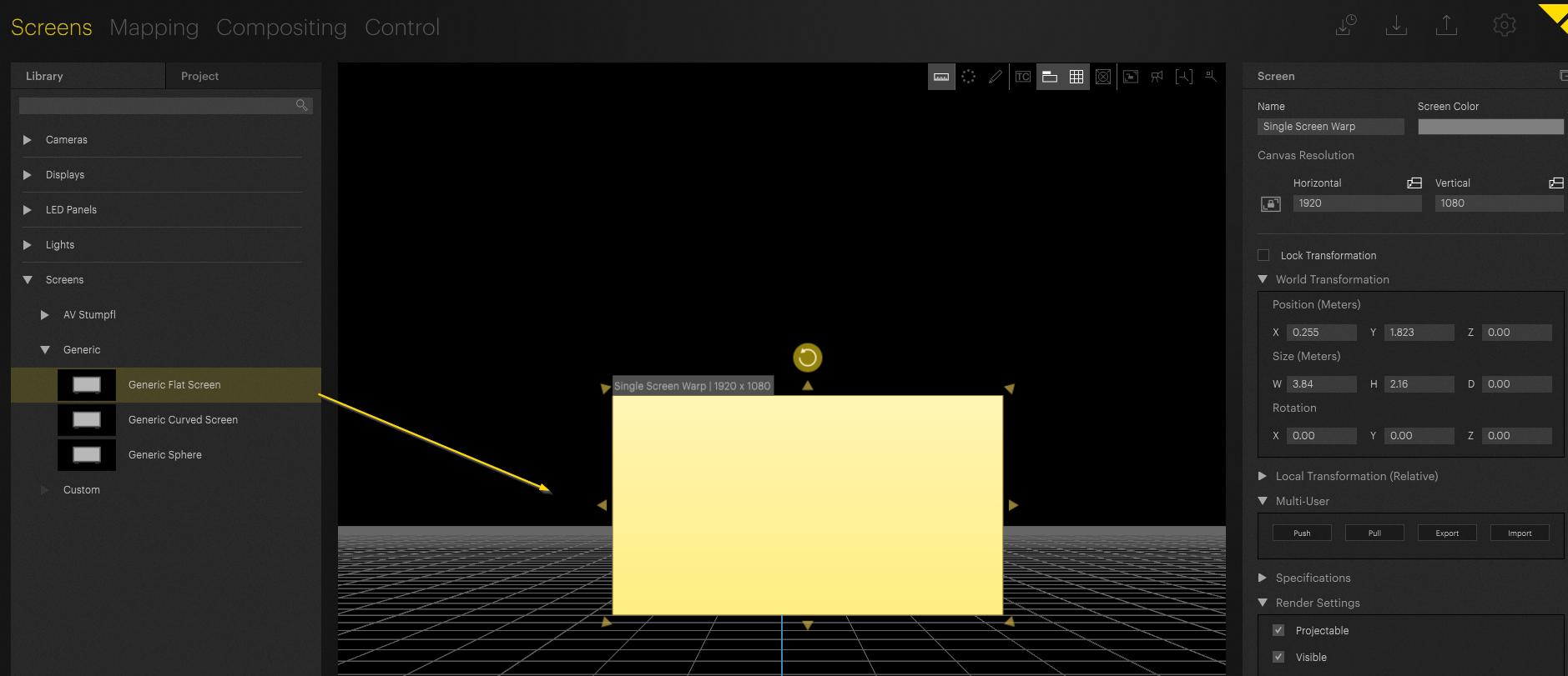
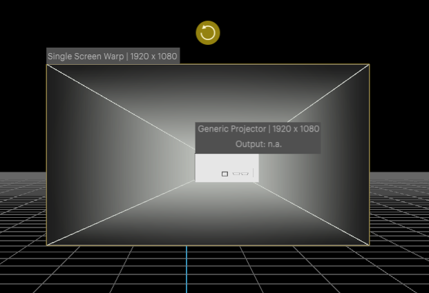
The first and easiest warping setup is one projector and one screen. We start by adding a screen to our project. In a project environment the screen must mirror the real world's screen dimension:
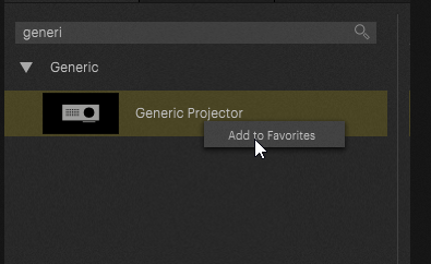
For demonstration purpose i selected the generic project. You can add projectors to your favorites by right clicking and adding them to your favorites:
Now we add the projector to the workspace: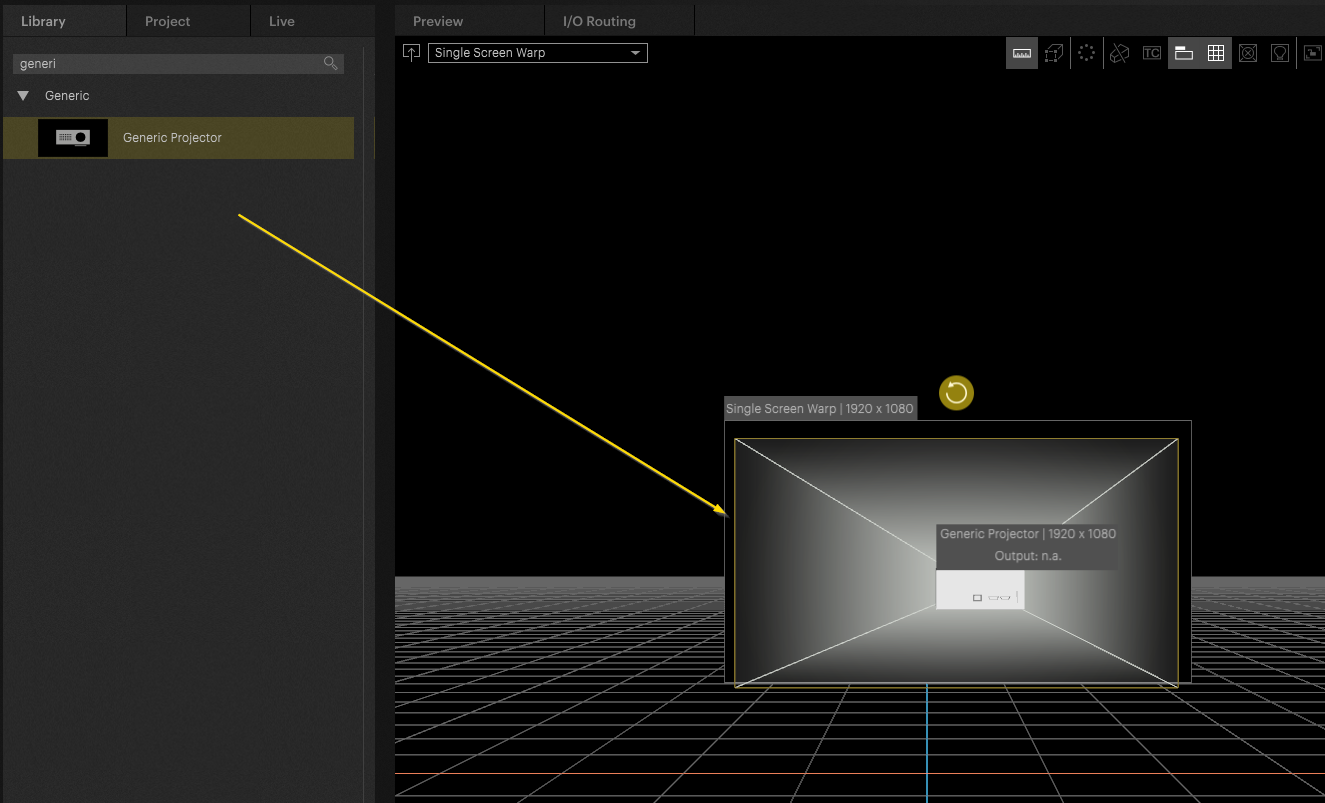
A simple tip to automatically align the projector perfectly to the screen is by using the auto transform tool.
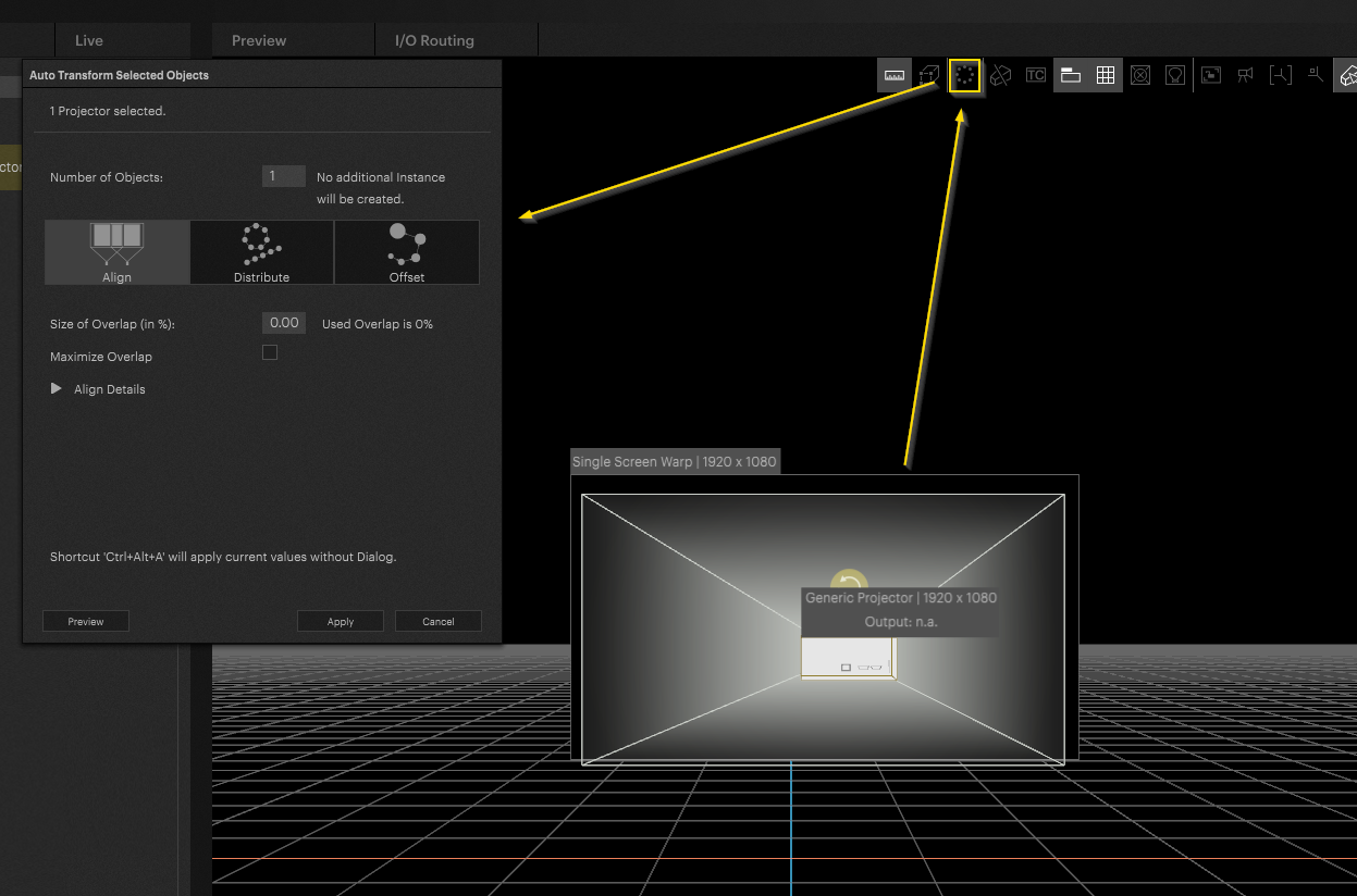
Quick tip:
Select the projector and press CTRL + ALT + A. This will trigger the auto align transformation via shortcut:
To help with warping we highly suggest activating the test pattern here:
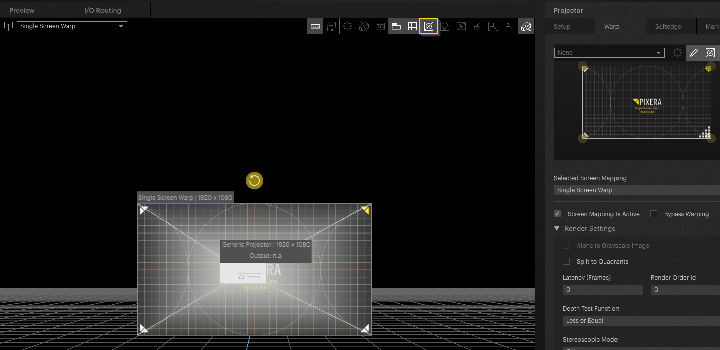
Warp - Settings overview
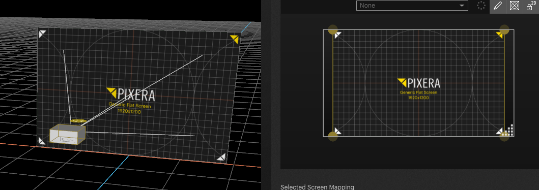
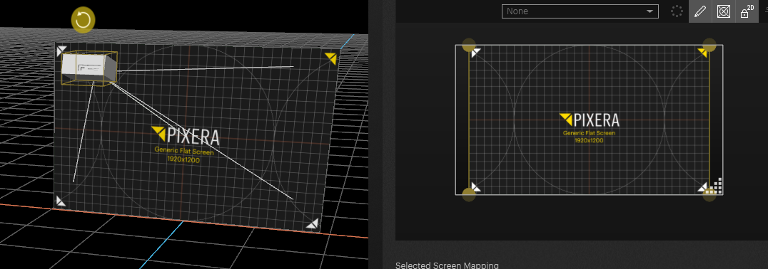
To start warping select the warp subcategory in the right-hand side inspector. It is possible to flip the warping window into the regular workspace. This helps with complex warping tasks:
Now lets take a look at the warp engine settings.
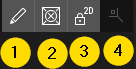
1: Edit mesh: switch between “Free Form Deformer (FFD)” or Vertex modifiers
2: Activate / Deactivate test pattern
3: Lock 2D - the warp Engine is its own 3D engine. Most of the time for regular projection warpings it is more useful to lock the interface to a 2D view
4: Reset view
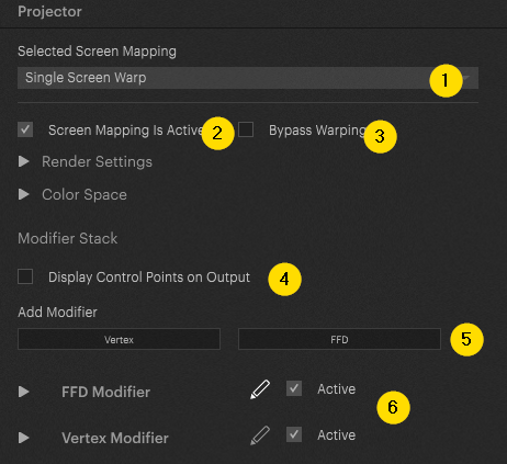
1: Drop Down for screen selection. In some cases, it may be necessary to warp into multiple screens shifted in the Z axis. This setting enables switching between those screens.
2: Deactivate the screen mapping.
3: Bypass the warp render pass. (Deactivating this setting improves the latency slightly)
4: Show War control Points on Output. By default, warp-points are not displayed on output.
5: Add additional Vertex and or FFD modifiers. More to this later.
6 Edit FFDs or Vertex modifiers. They can be deactivated as well.
FDD Modifiers
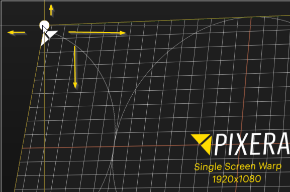
You can start the warping process by dragging the FFD points or by moving them by the arrow keys on the keyboard for more precise control:
Use “shift” + “arrow” keys to move larger distances
Use "alt "+"arrow" keys to change selection
Use "shift "+"alt"+"arrow" to add points to the selection.
FFD is the preferred warp mechanic for most of the projects. Let's look at the FFD settings. Expand the Settings to get access to the advanced options:
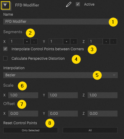
1: you can rename the FFD modifier. This can be useful when working with multiple modifiers of the same type.
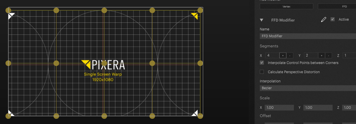
2: Add and/or remove modifiers. The number of modifiers is always going to double:
3: These options enables interpolation for control points within the edges. If deactivated the control points stay in place and don't move when moving the position of the edge points.
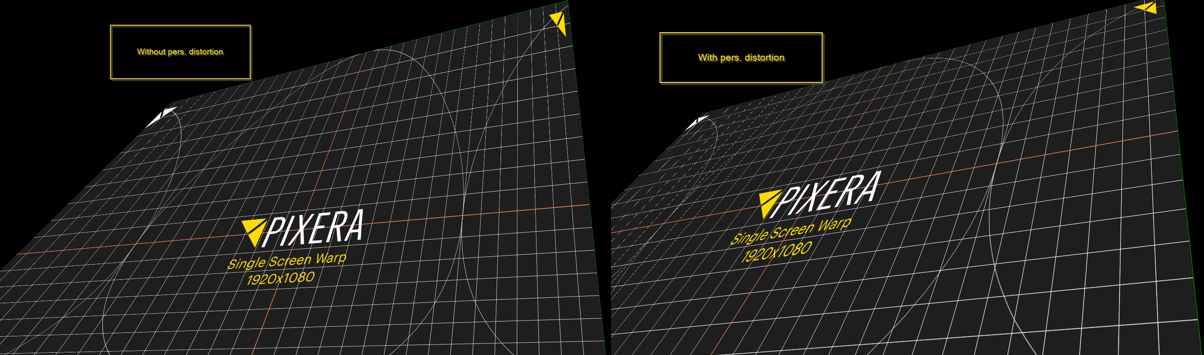
4: Calculate Perspective distortion as seen in this comparison:
5: Change interpolation method between Bezier and linear.
6: Scale down the FFD grid
7: Offset the FFD grid
8: Reset FFD points
Vertex Modifiers
Select them by pressing the pencil icon in the interface:
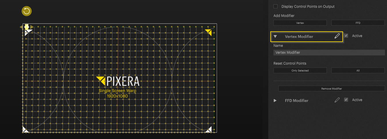
Vertex points can't be changed. They are determined by the composition of the underlying 3D model. Pixera´s internal screens do have a fixed set of vertex points. If you need screens with different vertex points it is advised to import custom 3D objects via the screens tab and work with those.
Adding additional modifier stacks
Pixera can add and / or remove additional warp layer modifiers. This allows for additional independent warp layers. This could be useful for more complex situations. For example, the task is to warp the facade of a building. Simply add additional modifiers for individual parts of the facade (e.g. windows):
Feed Modes
Now that we have looked at most of the warp settings it is important to discuss Feed Modes before discussing multi projector warp setups.
Feed Modes can be defined in the “Feed Areas” setting in the setup tab of the selected projector:
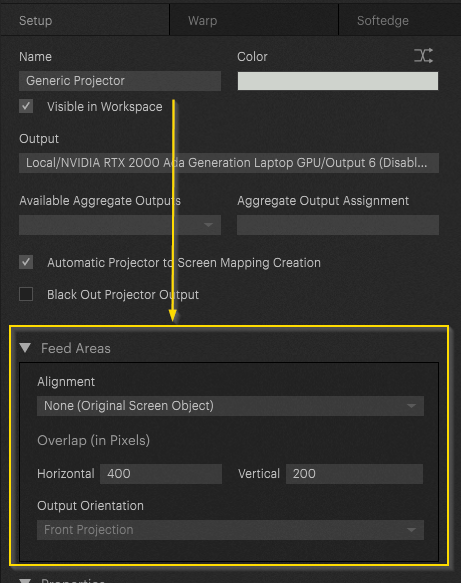
The default setting for “Feed Areas” is none. This setting is important when working with automated Softedge. Without “Feed Areas”, Softedge can't be calculated automatically.
PLEASE NOTE:
If you do projection onto a 3D model, and you get nothing but black on the output and see almost no vertices, try setting your feed mode to "none".
Explanation:
Setting the feed mode to none makes sense in most cases on 3D objects. The setting depends on the complexity of the surface and the UV coordinates. If you have non-continuous UV coordinates, you must set the feedmap to “none”. If you have continuous UV coordinates, but a complex surface (e.g. a house facade with many elements), it could be very tedious without “none”.
So now what is this setting for? To answer this, we must dig deeper. In Pixera we are working with 2 different dimensions. The pixel space and the real-world space with real world diameters. In addition to that we must consider perspectives as well. When the viewport of our projector hits the projection surface, depending on the setup and technical needs, we need to work with different approaches. Sometimes it is important to be pixel accurate. Sometimes it may be important to work with the correct perspective correction. To achieve this, feed modes can be utilized. Depending on the setting, the output on the warp engine may differ.
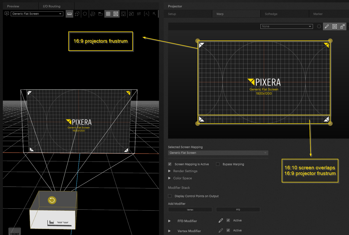
We are now going to look at the different modes. We start with a simple setup - one screen with a resolution of 1920x1200 pixel and one projector with a resolution of 1920x1080 pixel. As you may already have noticed the resolution of the screen and projector don't match. This is an important fact as it helps to highlight the “Feed Areas” as a feature.
“Feed Areas” are found in the setup tab when selecting a projector:
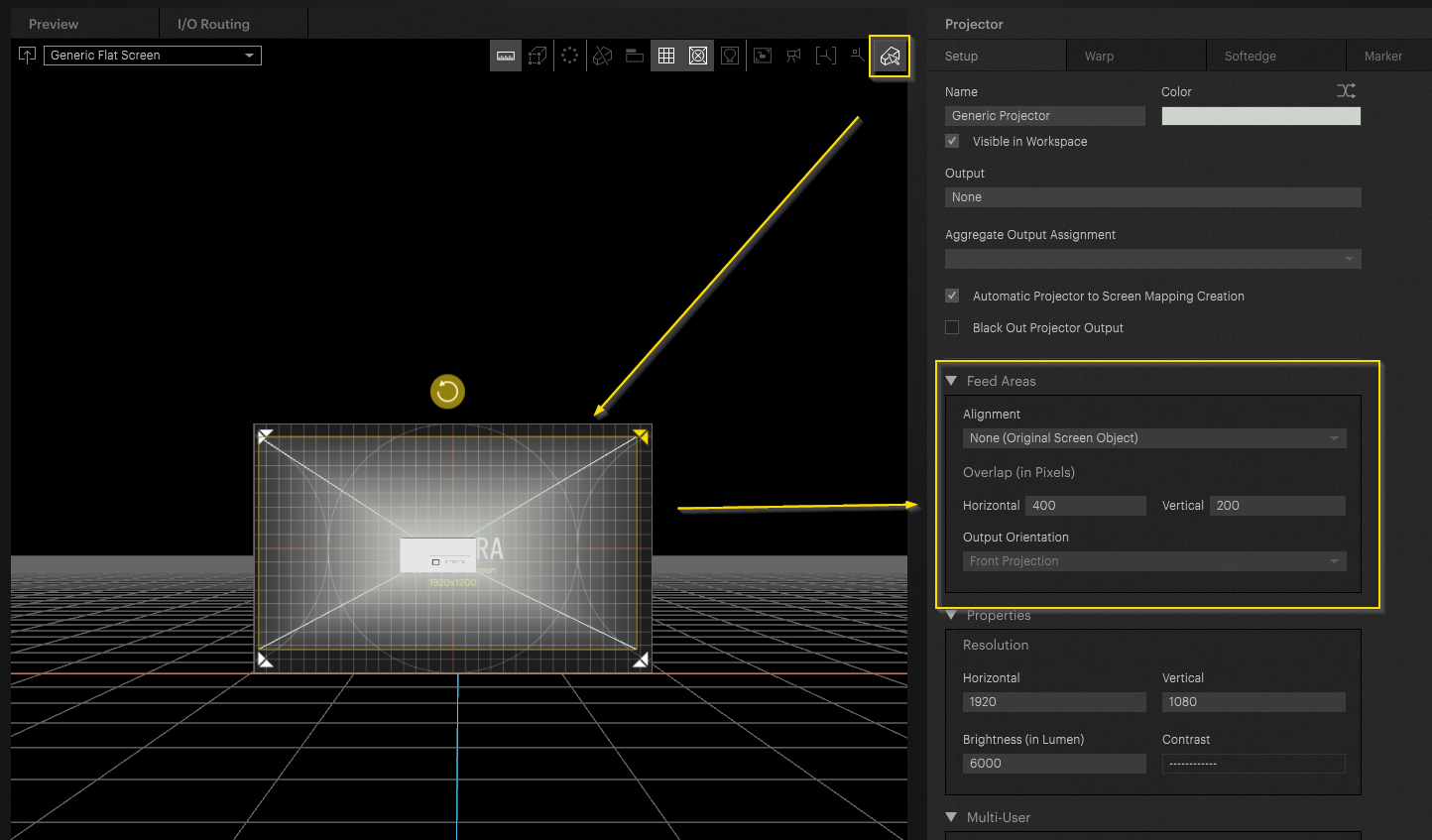
The default is None (Original Screen Object). None applies no automated feed area. It feeds the projectors viewport to the warp engine: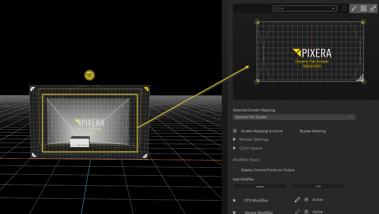
Info
The default setting can be changed in the Initial Values in the settings: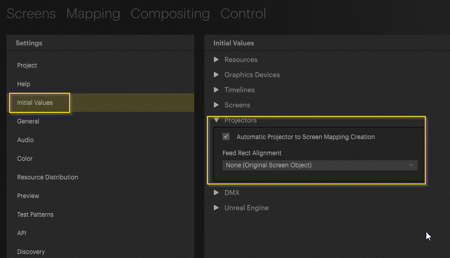
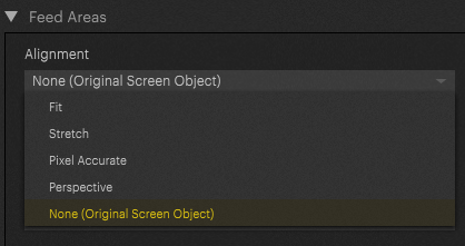
Let's look at the different modes available for setup:
If you have ever worked with the content scaling in the compositing tab the feed modes should feel familiar. On a basis it acts like content scaling. Though instead of scaling the content into the screen space, it scales screen object into the projectors frustrum. This will change the outcome in the warp tab. The warp engine is the projector's viewport. It is even its own 3D engine. You can deactivate the lock to 2D mode to pan / tilt the camera:
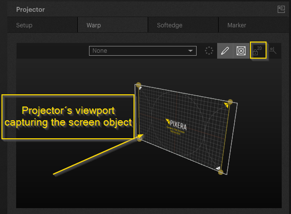
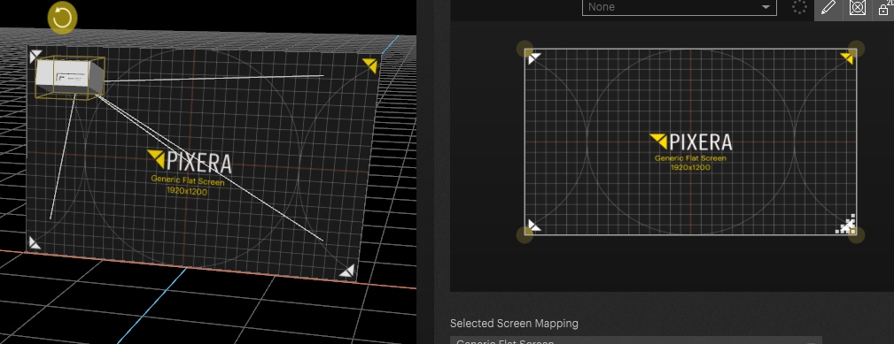
By changing the “Feed Mode” the visual representation will change as well in the GUI. When activating “Feed Modes” the project shows the screen it “feeds” its image to:
Fit - The screen object (16:10 - 1920x1200) is fit into the projectors frustrum (16:9 - 1920x1080):
No perspective distortion:
Stretch - Our 16:10 image is stretched onto the 16:9 frustrum of the projector:
Pixel accurate - As we our screens and projectors pixel ratio do not match a pixel accurate setup will look like this (without perspective distortion):
Stretch and Fit are not pixel accurate as the dimensions of the screen are being changed.
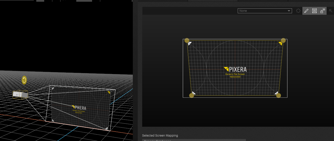
Perspective - this mode adds perspective distortion to the mix:
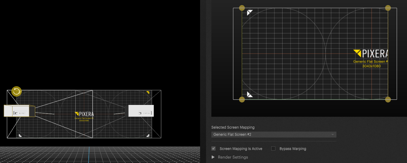
Multi Projector Setup
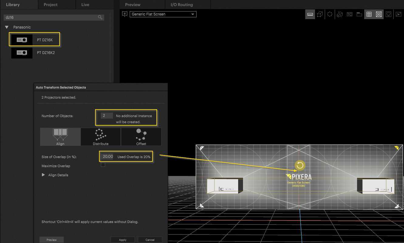
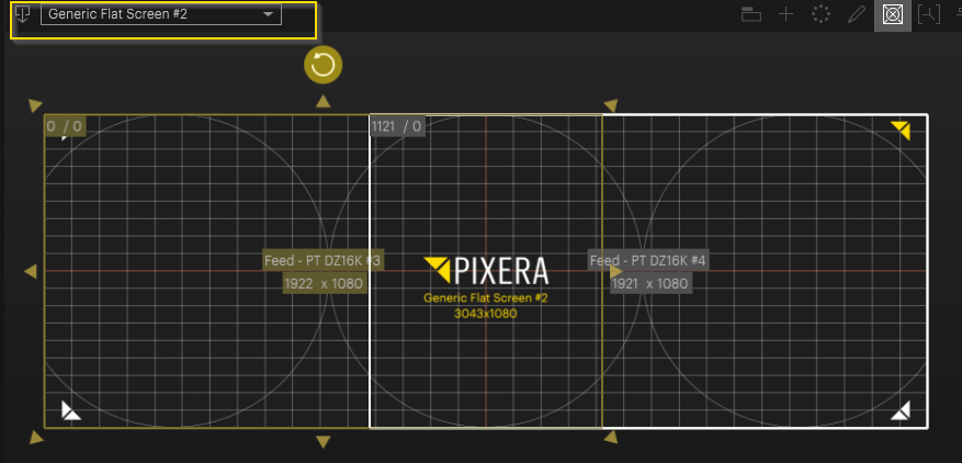
Now for the Multi Projector Setup we switched it up a little bit. For this demonstration, a widescreen of 3456x1080 pixel is being used:
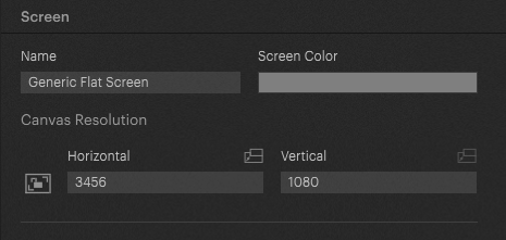
Two times 1920x1080 with 20% overlap horizontally. An ideal softedge-projection setup. We will now go through the principles already described and apply them to a multi projector setup.
Let's add a projector. In this case I chose a PTDZ16K with 1920x1080 pixel resolution (16:9). Add it to the screen. Let's align it with the help of the alignment tool:
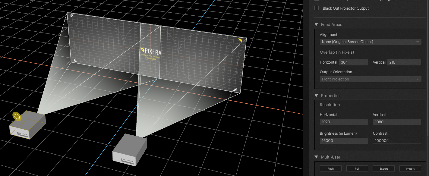
Feed Modes
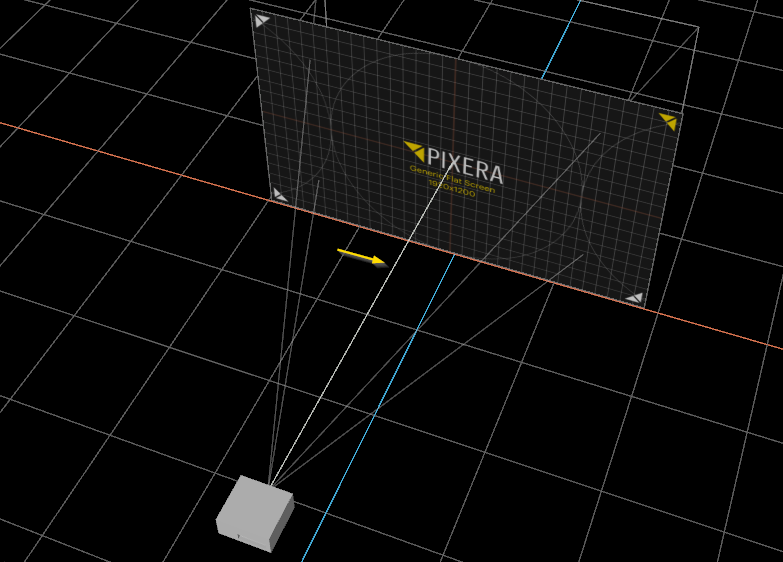
By default, Feed Modes are not applied which is also visible by the representation of the projectors frustrum:
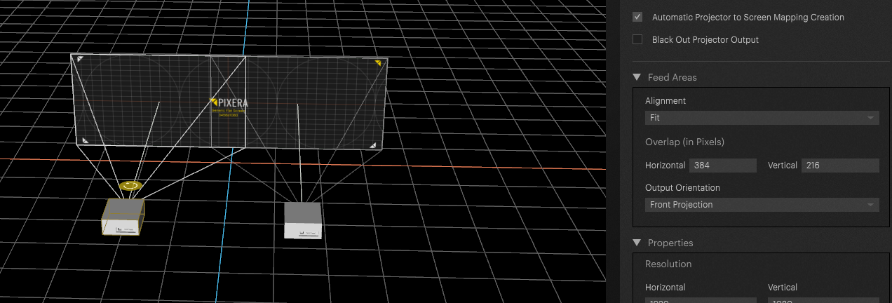
Now we change the setting to one of the feed mode presets. It is important to select all used projectors when changing this setting, otherwise the correct setting won't be applied:
Now the visual representation of the frustrum changes to feed modes:
Deep Dive Feed Modes technical aspects
We already took a first look at the basic principles of feed modes. Now let's look at what really is going on when using feed modes.
When using feed modes, the system applies the same mechanism when mapping LEDS: Output Mapping
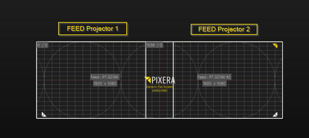
Rather than feeding the projectors viewport to the warp engine the system creates a “source feed” and slices this source feed according the the feed areas settings. In our case the source feed is equal to the screens resolution (3456x1080px) and these settings are applied:
To access the feed, select the projector and dive into the projector: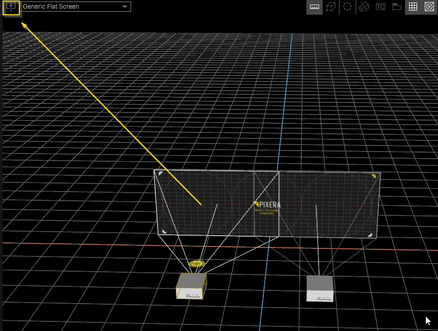
Like the output remapping for LEDs, we are now being presented with the feeds of the projectors. One could argue that the feed modes on projectors are LED remapping capabilities with added warping on top.
What's now happening is that Pixera is sending these feeds into the warp engine rather than capturing what's available through the projector's viewport.
In our case - as we have a proper projection setup - the feed “stretch fit and pixel accurate” will behave the same. Our projectors' resolutions fit perfectly into our widescreen as we have calculated an optimal overlap.
Let's look at a non-optimal setting and inspect the feed modes. In this case the resolution does not fit within the 20% overlap we want to use. 3D Workspace view:
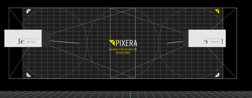
Dive in - Feed View:
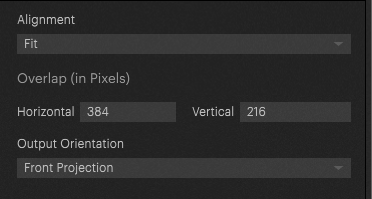
Feed Area set to fit:
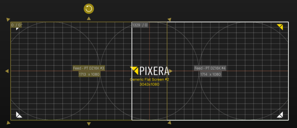
Feed Area set to stretch: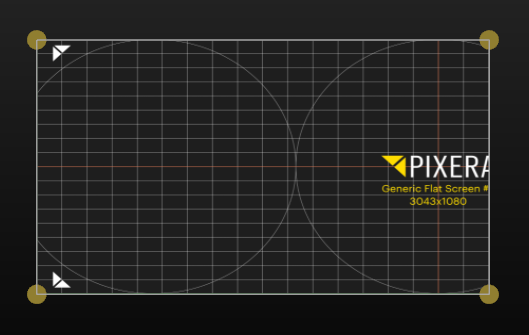
No let's change it up even more. As we have already seen, changing the projector's position does not affect the available warp feed of the projector. Instead, the available warp mesh is determined by the feed modes settings:
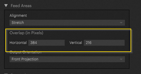
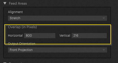
Pixera will take the resolution of the complete mesh and provide the warp feeds resolution by applying the overlap. Changing the overlap will change the feeds of the projectors:
– 384 Pixel Overlap:
vs 800 Pixel overlap:
Feed View after Dive in:
As can be seen the individual feed dimensions were increased by adjusting the softedge value in the feed modes options.
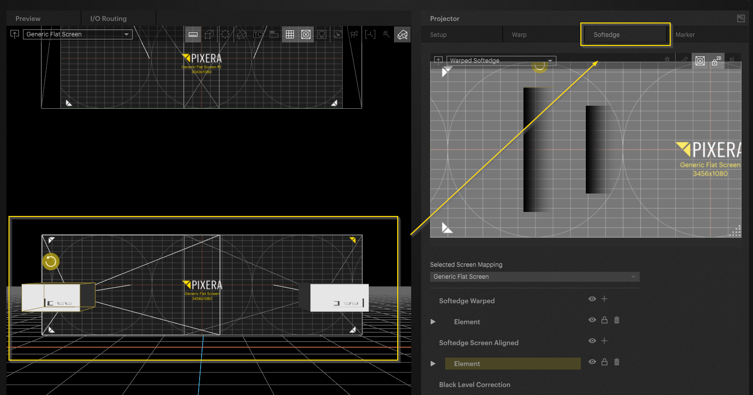
Softedge
Softedge Settings are available besides the War Tab in the projector's inspector:

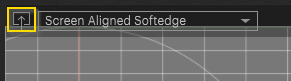
1 - Dive into Softedge. The regular view is the 3D workspace view of the screen or 3D model. By diving in the 2D texture can be accessed.
2 - Generate Auto Softedge: This is only available when using feed modes.
3 - Edit Mesh (Softedge)
4 - Display Testpattern
5 - Lock 2D
6 - reset Viewport
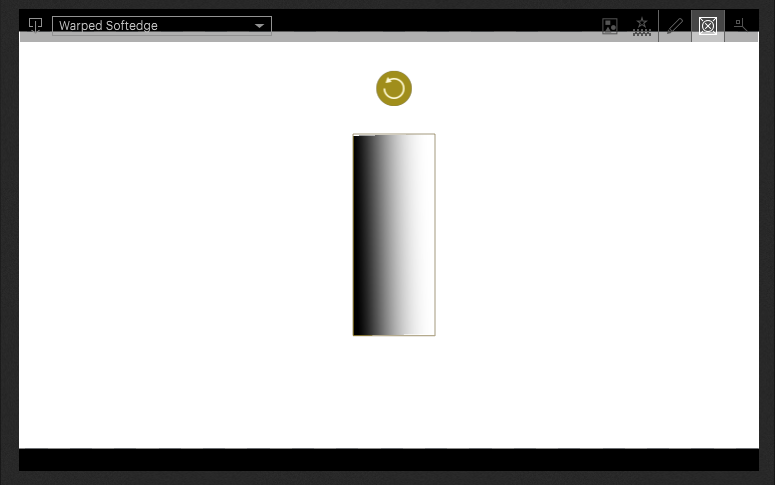
Generate Softedge is only available when using feed modes. After activating this button an auto softedge Mask is applied to the setup:
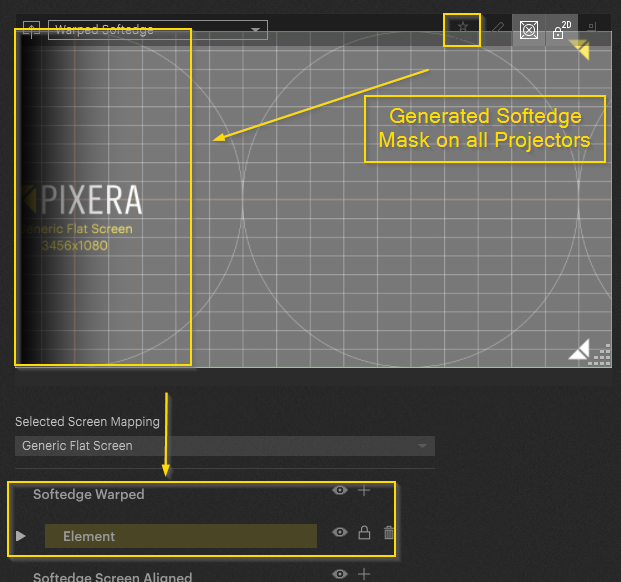
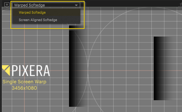
The just created softedge mask was created as a warped softedge element. In Pixera screen aligen and warped masks can be created. Automatically created softedge masks are always created as warped masks.
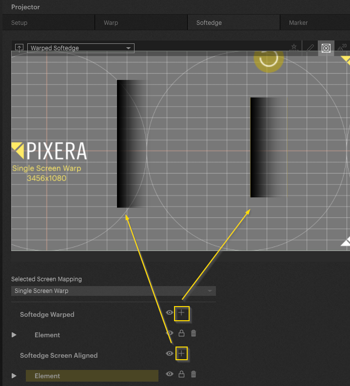
Manual Softedge
Besides the autp softedge creation process, softedge masks can be added manually as well. To do so select the desired projector and add the softege by pressing plus:
To modify them in the softedge inspector, select the desired softedge type in the softedge engine window:
Now looking at the softedge settings there is a lot we can modify:
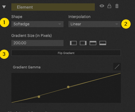
1: Change from Softedge to Mask
2: Switch interpolation mode
3: Gradient and Gamma Curve options
Especially when working with anything but flat objects diving in makes sense. When diving in we change into the pixel space of the projected screen. This helps aligning and modifying the softedge:
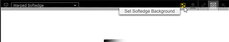
Furthermore, after diving in you can load in softedge background images by clicking this button. This enables the import of custom softedge masks from external sources:
Pixera 1.9.136 | 21. October 2023