 Contact Us


Important Information
Abbreviations and naming used in this manual
PIXERA one: PX1
PIXERA two: PX2 (if not explicitly mentioned otherwise, this also applies to models PX2 OCTO and Pixera two RS)
PIXERA two RS: PX2RS
The term "media server" is used in this manual for both media servers (PX1, PX2).
Identifying the product and other information
This instruction manual relates to media server and media player systems from AV Stumpfl GmbH.
The model designation and serial number are located on the media server’s serial number tag.
For PX1, the serial number tag is located on the bottom of the unit.
For PX2, the serial number tag is located on the sides in the recess on the back.
General information about this instruction manual
With this instruction manual, users of AV Stumpfl GmbH media servers are provided the necessary information for the safe use of their systems.
The safety instructions resulting from the legally prescribed risk analysis and assessment are an essential part of these instructions.
-
IMPORTANT! Please read these instructions carefully before using your system! Store this instruction manual in a safe place for later reference.
-
IMPORTANT! Due to the high number of possible configurations, it is not possible to provide specific instructions for all the individual components in this manual.
For specific questions and further support, please contact us at:
AV Stumpfl GmbH, Tel: +43 (7249) 42811, support@avstumpfl.com
Subject to change without notice. All information is provided without guarantee and liability.
Safety information
The safety information in this instruction manual can be broken down into the following categories:
-
WARNING is used for hazards that could result in death or serious injuries.
-
CAUTION is used for hazards that could result in minor injuries.
-
IMPORTANT is used for all other cases where the potential for material damage exists or specific actions are recommended.
Target group/qualifications
The use of media server systems requires specialist AV and IT knowledge. For this reason, the use of media server systems should be limited to qualified personnel. Media server system owners and operators must ensure this via organizational measures.
The qualified personnel responsible for installation and maintenance must also be able to prevent any remaining risks in terms of health and safety with their understanding of the existing dangers.
Warning about electrical hazards
Electrical hazards can arise across a media server system’s entire life cycle. These can arise not only from the media server system, but the electrical installation on site as well.
-
WARNING! Dangerous situations can arise from the careless handling of the server system or faulty electrical installation.
These can result in severe injury or death!
Intended use
The media server systems are meant exclusively for use in rooms with normal operating conditions (temperature, humidity, radiation) such as air-conditioned server rooms, offices and other rooms with similar conditions.
Warning about foreseeable misuse
-
WARNING! Dangerous situations can arise from using the server systems in unsuitable environments.
These can result in severe injury or death! -
WARNING! Dangerous situations can arise from unauthorized modifications.
These can result in severe injury or death!
Installation on site
Checking for transport damages
Check the packaging and the media server system for possible damage that could have arisen during transport. If you find damage, please report it immediately to your vendor or AV Stumpfl GmbH.
-
IMPORTANT! Add-on cards can sometimes become partially detached from their slots during transport.
In this case please report it immediately to your vendor or AV Stumpfl GmbH.
Danger from condensation
-
WARNING! A difference in temperature of 15°C between the room’s temperature and the media servers can lead to condensation. This can lead to short circuits and other damage. These can lead to the risk of electrocution. Electrocution can result in severe injury or death!
Danger from incorrect posture and overexertion
-
WARNING! Due to the weight and dimensions of the server system, physical danger can arise during set up and installation.
Danger from tipping
-
WARNING! The server system can tip over from improper transport or installation. This is particularly true for rack systems that have a high center of gravity due to their construction.
This can result in severe injury or death!
Installation on site
AV Stumpfl GmbH recommends installing the server in an air-conditioned server room. Select a site that is:
- Clean, dry and free of particles in the air (except for normal dust).
- Not near sources that cause vibrations or shaking.
- Protected from strong electro-magnetic fields that arise from electrical devices.
- Provides access to a properly grounded wall socket.
- Able to be equipped with surge protection, particularly in areas subject to thunderstorms.
- Provides sufficient space for access to the power cables, as these are the primary way to disconnect the server from the power supply.
- Provides sufficient space to ensure air circulation (for cooling).
Danger from noise
-
WARNING! Some server systems emit noise. Generally, this noise is produced by the system fans.
In certain situations, this can lead to hearing damage. Communication near such server systems can also be impaired.
Initial installation
Notes for rack system installations
Install a line disconnector for the entire rack system.
This line disconnector must be easily accessible and have a label that states that it controls the power supply to the entire unit and not just the servers.
Danger from improper voltage supply
-
WARNING! Dangerous situations can arise from improper voltages. These can lead to the risk of electrocution.
Electrocution can result in severe injury or death!
The server system can be operated in combination with an uninterruptible power supply (UPS). In this case, please follow the instruction manual for the UPS system!
Danger from improper grounding
-
WARNING! Dangerous situations can arise from improper grounding. These can lead to the risk of electrocution.
Electrocution can result in severe injury or death!
Proper grounding is also very important for protection against EMC interference.
Danger from fire
-
WARNING! Dangerous situations can arise from improper electrical installations. These can lead to the risk of fire.
Fires can result in severe injury or death!
Always consult the responsible specialists for such work.
Operation, maintenance, modifications, cleaning and disassembly
Electrical hazards
Incidents arising from electrical hazards can occur during operation, maintenance, when making modifications, cleaning or disassembling the server.
Turn off all connected peripheral devices before opening the media server system.
NOTE: Opening the media server system will void its warranty!
-
WARNING! Dangerous situations can arise if the server system is not turned off before opening the system.
These can result in severe injury or death!
Additional comments on the subject:
- The power button will NOT disconnect the system from the source of power. The server system must be completely disconnected from the source of power.
- To do this, all power cables must be removed from the electrical outlet.
- A system may be equipped with multiple power cables. In such cases, ensure that all power cables have been unplugged.
- Do not make any modifications to the power cable and do not use any cables except those with the correct specifications. Each power supply in the system must be connected to the power source via its own cable.
- Power supplies do not have any parts that can be serviced by the user.
- Never open a power supply. Power supplies contain dangerous voltages, currents and energy sources. Send the device back for any necessary maintenance work.
- The server system can unexpectedly restart after an interruption in the supply of power.
One exception is components that can explicitly be plugged in (hot-plug) or swapped (hot-swap) during operation. Please note the following safety instructions for hot-plug power supplies.
Electrical hazards related to hot-plug power supplies
Electrical accidents can occur when exchanging hot-plug power supplies.
-
WARNING! Dangerous situations can arise from the careless handling of hot-plug power supplies.
These can result in severe injury or death!
Avoiding data loss
-
IMPORTANT! Remember to backup your data before performing any maintenance or any other similar work inside your media server system.
Check to ensure that your data restoration system works properly.
Disassembly and assembly of the housing
Should you need to remove the media server system’s housing for maintenance work or any similar work inside the system, make sure to store all screws and fastenings in a safe place.
NOTE: Opening the media server system will void ins warranty!
Once you have completed your work on the media server system, reassemble the housing using the original screws and fasteners.
- IMPORTANT! Operating the system without its case can lead to damage for the system components.
Reattach the case as follows:
1. First, ensure that you have not left any tools or other parts in the system!
2. Check whether all cables, add-on cards and other components are correctly configured and attached.
3. Re-mount the panels onto the product’s frame!
Danger from sharp corners and edges
-
CAUTION! Despite careful selection of the components, sharp corners and edges can occur on the sheet metal housing. Plastic parts can also break during assembly or disassembly and leave sharp corners and edges.
Injuries can be the result. - Work with care and avoid sharp corners and edges.
- Wear protective gloves especially when working on the housing and when installing rack systems!
Danger of pinching
-
CAUTION! Moving parts can pinch fingers. Injuries can result!
Danger from hot components
-
WARNING! During operation, the processor and heat sink can get very hot. Burns can result.
Danger from moving parts
-
WARNING! Server systems contain moving parts, such as rotating fan blades.
Contact with such components can cause injury.
Danger from batteries
-
WARNING! A danger of explosion and corrosion can arise from improper battery replacements. Hazardous substances can be leaked.
Improper use can result in serious injury.
Preventing damage caused by a lack of ESD measures
-
IMPORTANT! Electrostatic discharge can damage electronic components, circuit boards and other components.
Perform all work at an ESD workstation!
If such a workspace is not available, you can achieve a degree of protection against electrostatic discharge by wearing an anti-static wristband. You can use these to keep you grounded by attaching the clip to any unpainted metal part of your computer case.
Always handle circuit boards with utmost caution. They are extremely sensitive to electrostatic discharge. Hold circuit boards by the edges.
After removing the circuit board from its protective case or the server, place it right side up on a grounded, fully discharged surface. We recommend the use of a conductive foam pad and not the board’s protective case.
Never drag the board across a surface.
Use gloves when working with sensitive components.
Preventing damage due to improper cooling and a lack of air flow
-
IMPORTANT! Make sure that all cooling fins of the heat sink and/or the ventilation slots are not covered.
Route all cables carefully to avoid disturbances in the air flow and avoid cooling problems.
To ensure proper cooling and air flow, only operate the system with its case fully assembled.
Preventing damage caused by unsuitable cleaning agents
-
IMPORTANT! Only use suitable cleaning agents.
A microfiber cloth is suitable for external cleaning.
Compressed air may be used to clean the inside of the server system. Please ensure that the air is applied gently and from a sufficient distance, as the components can otherwise be damaged.
Vacuum cleaners are not suitable for cleaning the inside of the media server system.
Instructions for disposal
The media server system and batteries must be properly disposed of as electrical waste at the end of their use. The disposal of electrical and electronic equipment is regulated by law. Please observe all local regulations. Disposal via household waste or ordinary industrial waste is not permitted.

Many of the materials are reusable. By following this notice, you make an important contribution to protecting the environment.
Specifications
To ensure proper operation, make sure that the following operating conditions are met for the media server.
- IMPORTANT! When you receive your media server, place it in the environment where you will install it. Leave the server in its shipping crate at its final destination for 12 hours and do not connect it to the power supply! This resting period prevents thermal shock and condensation.
Ambient temperature
An ambient temperature range of 21°C to 23°C is optimal for server reliability. This temperature range allows the recommended relative humidity level to be maintained quite easily. The maximum admissible temperature range is between 10°C and 30°C. Please bear in mind that high temperatures have a negative effect on the components’ life cycle.
Relative humidity
Ambient relative humidity levels between 45% and 50% are the most suitable for data processing operations.
- Prevent corrosion
- Provide an operating time buffer in the event of environmental control system failure.
- Help avoid failures caused by the intermittent interference from static discharges that occur when relative humidity is too low.
The maximum admissible relative humidity range is between 20% and 80% (noncondensing).
Airflow considerations
- Ensure that ventilation openings, such as cabinet doors, for both the inlet and exhaust of the server provide a minimum open area equal to the server’s open areas.
- Take care to prevent recirculation of exhaust air within a rack or cabinet.
- Manage cables to minimize interfering with the server exhaust vent.
In case the lighting effect device is equipped with fans:
- Ensure unobstructed airflow through the chassis. Ensure that air enters at the front of the server housing. Ensure that air exits at the openings designated for this purpose:
PX1: back and top, PX2: back.
Scope of delivery
PX1: 19" Rail Kit, Power Cable, Manual
PX2: 19" Rail Kit, 2x Power Cable, Manual
PX2 OCTO: 19" Rail Kit, 2x Power Cable, Manual
Warranty
We offer 2 years warranty on PIXERA media servers. An additional warranty of total 3, 4 or 5 years is available on request. IMPORTANT! Please note that opening or modifying the media server voids its warranty.
Environmental specifications – operating
Temperature (altitude less than 1000m, no direct sunlight) |
10°C to 30°C |
Maximum Temperature Gradation |
10°C per hour |
Temperature De-Rating (altitude more than 1000m) |
Reduce max. temp. by 1°C per 300m |
Maximum Altitude |
3000m |
Relative Humidity (noncondensing) |
20%RH to 80%RH |
Maximum Humidity Gradation |
10%RH per hour |
Environmental specifications – storage
Temperature (no direct sunlight) |
-30°C to 55°C |
Maximum Temperature Gradation |
20°C per hour |
Relative Humidity (noncondensing) |
5%RH to 95%RH |
Maximum Humidity Gradation |
10%RH per hour |
Power supply
PX1 |
PX2 |
PX2 RS |
|
Power Supply |
100-240VAC, 50-60Hz |
||
Power Consumption Peak |
500W |
800W |
800W |
Power Consumption Average with High Load * |
350W |
450W |
600W |
Redundant Power Supply Hot-Plug |
Not available |
Yes |
Yes |
PX1 |
PX2 |
PX2 RS |
|
Power Consumption Average with High Load * |
+35W |
Standard Config |
Standard Config |
Power Consumption Average with High Load * |
Not available |
+70W |
+70W |
Power Consumption Average with High Load * |
Not available |
+100W |
+100W |
* Power Consumption Average with High Load = Tested with very high CPU, GPU and storage workload.
Heat dissipation
PX1 |
PX2 |
PX2 RS |
|
Heat Dissipation Peak |
1710BTU/h |
2430BTU/h |
2430BTU/h |
Heat Dissipation Average with High Load * |
1200BTU/h |
1540BTU/h |
2050BTU/h |
PX1 |
PX2 |
PX2 RS |
|
Heat Dissipation Average with High Load * |
+120BTU/h |
Standard Config |
Standard Config |
Heat Dissipation Average with High Load * |
Not available |
+240BTU/h |
+240BTU/h |
Heat Dissipation Average with High Load * |
Not available |
+341BTU/h |
+680BTU/h |
* Heat Dissipation Average with High Load = Tested with very high CPU, GPU and storage workload
Physical
PX1 |
PX2 |
|
Case Dimension (WxDxH) |
447 x 441 x 44,4mm |
445 x 468 x 88,9mm |
Max. Product Dimension (WxDxH)* |
484 x 489 x 44,4mm |
484 x 493 x 88,9mm |
Power Supply Dimension (WxDxH)* |
- |
- |
Product Weight |
8,3kg |
13,1kg |
Power Supply Weight |
- |
- |
Shipping Dimension |
660 x 580 x 160mm |
790 x 560 x 220mm |
Shipping Weight |
11,75kg |
21,15kg |
PX1 with rails fit into a rack with a depth between 675mm and 850 mm.
PX2 with rails fit into a rack with a depth between 675mm and 920mm.
Dimensions
IMPORTANT! Please note that due to the production process there may be deviations in the dimensions. For exact dimensions please use the measures of the actual device.
Dimensions PX1

Dimensions PX2
Front views
Front view PX1

Front view PX2

Rear views
Rear view PX1

Rear view PX2

Description rear views PX1, PX2
IPMI LAN:
The IP address of the IPMI LAN port is similar to the IP address of LAN1 (see [6] below), but instead of 10.31.x.x. the address is 10.41.x.x. For example, if LAN1 has the address 10.31.2.3, the IPMI LAN port has the address 10.41.2.3.
2x 10Gbps LAN:
Full-duplex speeds of 100 Mbit/s, 1 Gbit/s and 10 Gbit/s are supported, 10Mbps and below are not supported!
Viewed from the back of the server, the left port is named LAN1 in the operating system and is configured with a fixed IP address which is printed on the serial number label.
The port on the right is named LAN2 and is configured that it obtains its address via DHCP.
Please note that these are the IP addresses of the delivery state of the media server. All IP addresses can of course be changed individually.
Options PX1, PX2
Performance upgrade
The Performance Options consist of a faster CPU and more RAM. More RAM also uses more RAM channels and thus increases data throughput.
- Option Code: X24, X50, X64
Option Slot PX1: no slot needed
Option Slot PX2: no slot needed
Standard Configuration:
Standard Configuration for |
PX1 |
PX2 / PX2 RS |
PX2 Octo |
Option Name |
Xeon 14, 64GB RAM |
Xeon 24, 128GB RAM |
Xeon 50, 128GB RAM |
Code |
X14 |
X24 |
X50 |
Server Grade Hardware Components |
Yes |
Yes |
Yes |
CPU Type |
Intel Xeon SP |
Intel Xeon SP |
Intel Xeon SP |
CPU Performance Index |
17 |
24 |
50 |
CPU # of Cores / # of Threads |
8/8 |
12/24 |
24/48 |
CPU Min/Max Frequency |
1,8/1,9GHz |
2,0/3,9GHz |
2,1/3,9GHz |
RAM |
64GB |
128GB |
128GB |
RAM Channels used (max. 6) |
4 |
8 |
8 |
ECC RAM |
Yes |
Yes |
Yes |
Performance Upgrades available:
Available for |
PX1 |
PX2 |
PX2 |
Option Name |
Xeon 24, 128GB RAM |
Xeon 50, 128GB RAM |
Xeon 64, 128GB RAM |
Code |
X24 |
X50 |
X64 |
Server Grade Hardware Components |
Yes |
Yes |
Yes |
CPU Type |
Intel Xeon SP |
Intel Xeon SP |
Intel Xeon SP |
CPU Performance Index |
24 |
50 |
64 |
CPU # of Cores / # of Threads |
12/24 |
24/48 |
24/48 |
CPU Min/Max Frequency |
2,0/3,9GHz |
2,1/3,9GHz |
2,0/3,4GHz |
RAM |
128GB |
128GB |
128GB |
RAM Channels used (max. 6) |
8 |
8 |
8 |
ECC RAM |
Yes |
Yes |
Yes |
Storage options
Please note that on PX1 and PX2 the Operating System is stored on a separate, so the capacity of the data SSD is fully available.
Option Slot PX1: no slot needed
Option Slot PX2: no slot needed
PX1 Single U.2 SSD:
Optional SSD for data. Installed internally in PX1.
- Code U3T8-1, U7T6-1, U15T-1
Available for |
PX1 |
||
U.2 SSD Capacity (Net) |
3,84GB |
7,68TB |
15,36TB |
U.2 SSD Max. Constant Read Rate |
5GB/s |
5GB/s |
5GB/s |
PX2 Dual U.2 SSD in RAID0:
Optional 2x SSDs in RAID0 for data. Installed in primary and secondary data SSD slot.
- Code U3T8-R0-2, U7T6-R0-2, U15T-R0-2, D30T-R0-2
Available for |
PX2 |
|||
U.2 SSD Capacity (Net) |
3,84TB |
7,68TB |
15,36TB |
30,72TB |
U.2 SSD Max. Constant Read Rate |
10GB/s |
10GB/s |
10GB/s |
10GB/s |
Please note, that the above options cannot be combined.
Video Outputs
Video Outputs are always supplied with the Server.
- Option Code: RA4
Option Slot PX1 and PX2: FP1 (standard, cannot be changed)

Port description
OUT A, …, OUT D: Video Output 1, …, Video Output 4
- Video output standard: DP1.4a
- Video output resolution (max.): 7680x4320
- EDID management: Yes
IMPORTANT! Please note that due to space reasons DisplayPort cables need to be used where the plug does not exceed a maximum thickness of approx. 14mm!
Video Outputs for PX2 OCTO
- Option Code: RA8
Option Slot PX1: Option not available
Option Slot PX2: FP1, FP2 (standard, cannot be changed)

Port description
OUT A, …, OUT H: Video Output 1, …, Video Output 8
- Video output standard: DP1.4a
- Video output resolution (max. per Output): 5120 x 2880 @60Hz
- EDID management: Yes
IMPORTANT! Please note that due to space reasons DisplayPort cables need to be used where the plug does not exceed a maximum thickness of approx. 14mm!
Output option: GUI Output
Quad channel GUI output.
- Option Code: G2
Option Slot PX1: LP1
Option Slot PX2: FP5
Port description
GUI D, C, B, A: GUI Output 4, 3, 2, 1
- GUI Output Standard: mDP1.4a
- Max GUI Output Resolution (max. per Output): 5120 x 2880 @ 60Hz
Output option: Framelock and Genlock
Framelock and genlock input and outputs.
- Option Code: S2
Option Slot PX1: FP2
Option Slot PX2: FP4

Port description
IMPORTANT! Do not connect to LAN! This will damage the sync card and the LAN equipment!
FL0, FL1: Framelock 0/1 Input/Output
- LED yellow: Port is an output, but no signal is present
- LED green: Port is an input, but no signal detected
- LED yellow flashing: Port is an output and sending a signal, the frequency of the blinking is the refresh rate of the signal
- LED green flashing: Port is an input and receiving a signal, the frequency of the blinking is the refresh rate of the signal
FS: Framelock Sync Status LEDs
Shows the synchronization status of the connected video output card. The topmost LED is dedicated to video output card 1 (installed in all servers) and the second LED to video output card 2 (if installed).
- LED off: Video output card not connected. This indicates a technical problem – please contact us.
- LED yellow: Video output card not synchronized.
- LED green: Video output card synchronized.
- LED yellow flashing: Video output card synchronized, but within 5% of the threshold of losing sync.
- LED green flashing: Video output card is synchronizing.
SP: Stereo Phase Status LEDs
Shows the active stereo status of the connected video output card. The topmost LED is dedicated to video output card 1 (installed in all servers) and the second LED to video output card 2 (if installed).
- LED off: Stereo not active.
- LED green: Stereo locked.
- LED green flashing: Stereo in process of locking.
GL: Genlock Input/Output
Live input option: IH2
Dual channel HDMI 2.0b input.
- Option Code: IH2
Option Slot PX1: LP1
Option Slot PX2: FP5, FP6

Option Slot PX2: FP2, FP3
Port description
HDMI-IN 1, HDMI-IN 2: HDMI Input 1, HDMI Input 2
- Video formats: PAL, NTSC, 720p, 1080i, 1080p, 2160p (4K-DCI or UHDTV)
- Graphic formats: VGA, SVGA, XVGA, WXGA, WXGA+, UXGA, WUXGA, WSXGA
- RGB 4:4:4, YUV 4:4:4, YUV 4:2:2, YUV 4:2:0
- 8-bit, 10-bit, 12-bit, 16-bit
- Frame rates from 23.98Hz to 120Hz depending on formats
Live input option: IS2
Dual channel 3G-SDI input
- Option Code: IS2
Option Slot PX1: LP1
Option Slot PX2: FP3, FP5

Port description
3GSDI-IN 1, 3GSDI-IN 2: 3G-SDI Input 1, 3G-SDI Input 2
- Video Interfaces:
- 3Gbps SDI (ST 424) Level A and Level B-DL (ST 425-1)
- HD-SDI (ST 292)
- Dual-Link HD-SDI (ST 372)
- SD-SDI (ST 259)
- Video Formats:
- SD: 625i50 (PAL), 525i59.94 (NTSC)
- HD 1280x720: 720p60, 720p59.94, 720p50, 720p30, 720p29.97, 720p25, 720p24, 720p23.98
- HD 1920x1080: 1080i60, 1080i59.94, 1080i50, 1080p30, 1080p29.97, 1080p25, 1080p24, 1080p23.98, 1080p60 A/B, 1080p59.94 A/B, 1080p50 A/B, 1080p60, 1080p59.94, 1080p50.
Live input option: IS4
Quad channel 3G-SDI capture card
- Option Code: IS4
Port description
3GSDI-IN 1, …, 3GSDI-IN 4: 3G-SDI Input 1, …, 3G-SDI Input 4
- Video Interfaces:
- 3Gbps SDI (ST 424) Level A and Level B-DL (ST 425-1)
- HD-SDI (ST 292)
- Dual-Link HD-SDI (ST 372)
- SD-SDI (ST 259)
- Video Formats:
- SD: 625i50 (PAL), 525i59.94 (NTSC)
- HD 1280x720: 720p60, 720p59.94, 720p50, 720p30, 720p29.97, 720p25, 720p24, 720p23.98
- HD 1920x1080: 1080i60, 1080i59.94, 1080i50, 1080p30, 1080p29.97, 1080p25, 1080p24, 1080p23.98, 1080p60 A/B, 1080p59.94 A/B, 1080p50 A/B, 1080p60, 1080p59.94, 1080p50
- 2K 2048x1080: 1080p30, 1080p29.97, 1080p25, 1080p24, 1080p23.98, 1080psf30, 1080psf29.97,1080psf25, 1080psf24, 1080psf23.98, 1080p60, 1080p59.94, 1080p50, 1080p48,1080p47.952
- 4K 3840x2160 (8 or 10-bit, Square Division): 2160p60, 2160p59.94, 2160p50, 2160p30, 2160p29.97, 2160p25, 2160p24, 2160p23.98
- 4K 4096x2160 (8-bit only, Square Division): 2160p50, 2160p30, 2160p29.97, 2160p25, 2160p24, 2160p23.98
Live input option: CT1H1
Mixed 12G SDI and HDMI 2.0b capture and playout card
- Option Code: CT1H1
Option Slot PX1: LP1
Option Slot PX2: FP3,FP5, FP6

Live input option: CT4
12G SDI capture and playout card
- Option Code: CT4
Option Slot PX1: LP1
Option Slot PX2: FP3,FP5, FP6
Port description
IMPORTANT! As this option does not have BNC connectors for space reasons, DIN-BNC adapters are required for operation with BNC cables.
- Blackburst or tri-level sync reference input
- SDI Video Interfaces and Formats:
CT4 I/O 1 - 8
CT1H1 I/O 1 – 4
- HD_292_1: S296M_720p_50Hz, S296M_720p_60Hz, S274M_1080p_24Hz, S274M_1080p_25Hz, S274M_1080i_50Hz, S274M_1080i_60Hz
- HD_DUAL_372: S274M_1080p_50Hz, S274M_1080p_60Hz
- 3G_A_425_1: S274M_1080p_50Hz, S274M_1080p_60Hz
- 4XHD_QUADRANT: 3840x2160p_24Hz, 3840x2160p_25Hz, 3840x2160p_30Hz
- 4X3G_A_QUADRANT: 3840x2160p_50Hz, 3840x2160p_60Hz
- 3G_B_DL_425_1: S274M_1080p_50Hz, S274M_1080p_60Hz
- 4X3G_B_DL_QUADRANT: 3840x2160p_50Hz, 3840x2160p_60Hz
- 2X3G_B_DS_425_3: 3840x2160p_24Hz, 3840x2160p_25Hz, 3840x2160p_30Hz
- 4X3G_A_425_5: 3840x2160p_50Hz, 3840x2160p_60Hz
- 4X3G_B_DL_425_5: 3840x2160p_50Hz, 3840x2160p_60Hz
- SDI Video Interfaces and Formats:
CT4 I/O 5 - 8
CT1H1 I/O 1
1x12G: 3840x2160p_60HZ or 4096x2160p_60Hz, in 8 or 10-bit
- HDMI-IN 1,
Network Interface Card Options
The naming of the network ports of the additionally installed network cards depends on the options installed in the server and are numbered consecutively starting with LAN3. All additional network ports are configured that they obtain an IP address from a DHCP server.
Network Interface Card Option: Quad 1Gbit/s
Quad channel 1Gbit/s network interface card
- Option Code: L1x4
Option Slot PX1: FP2, LP1
Option Slot PX2: FP3, FP5, FP6
Network Interface Card Option: Dual 25Gbit/s
Dual port 25Gbit/s network interface card
- Option Code: L25x2
Option Slot PX1: FP2, LP1
Option Slot PX2: FP3, FP5, FP6
Audio output option: HDSPe AIO Pro
RME HDSPe AIO Pro sound interface.
- Option Code: A1
Option Slot PX1: LP1
Option Slot PX2: FP3

Port description
Breakout 1: Breakout cable for Analog input/output and MIDI input/output
- The 15-pin analog breakout cable has four RCA connectors (stereo analog I/O), a 1/4" TRS jack (headphones), and two 5-pin DIN connectors (MIDI I/O).
- Using the optional balanced analog XLR breakout cable, the card offers balanced Line inputs and outputs via female and male XLR connectors.
Breakout 2: Breakout cable for SPDIF input/output and AES input/output
- The 9-pin digital breakout cable has two RCA connectors as coaxial SPDIF input/output (the red phono socket is the output), and an XLR AES/EBU input and output.
ADAT IN, ADAT OUT: Optical ADAT input and output
IMPORTANT! Due to the limited space at PX1 it can be possible that special cables for some connectors have to be used!
(More details see RME manual: https://rme-audio.de/downloads/hdspeaiopro_e.pdf )
Mechanical installation
This section provides information on installing the media servers.
There are a variety of rack units on the market, which may mean that the assembly procedure will differ slightly from the instructions provided. You should also refer to the installation instructions that came with the rack unit you are using.
-
CAUTION! Never mount the media server solely on the 19" mounting bracket attached to the server. This will break the 19" mounting bracket and damage the server, the rack and may cause injury.
-
CAUTION! Do not pick up the server with the front handles. They are designed to pull the chassis from a rack only. This may damage the server and may cause injury.
Precautions
- Ensure that the leveling jacks on the underside of the rack are fully extended to the floor, with the entire weight of the rack resting on them.
- For single rack mounting, stabilizers must be attached to the rack.
- For multiple racking systems, the racks must be coupled together.
- Always make sure that the rack is stable before pulling a component out of the rack.
- You may only extend one component at a time - the simultaneous extension of two or more components can cause the rack to become unstable.
- The units must be installed in a rack in such a way that no dangerous condition arises due to uneven mechanical loading.
- Install the heaviest server components on the bottom of the rack first, and then work your way up.
- Use an uninterruptible power supply (UPS) to protect the server from power surges and voltage spikes and keep your system up and running in the event of a power failure.
Mounting the Rail Kit on PX1
The package contains two rack rail assemblies in the rack mounting kit.
Each assembly consists of two parts: an inner fixed chassis rail attached directly to the server chassis and an outer fixed chassis rail attached directly to the rack itself.
Note: These rails fit into a rack with a depth between 675mm and 850 mm.
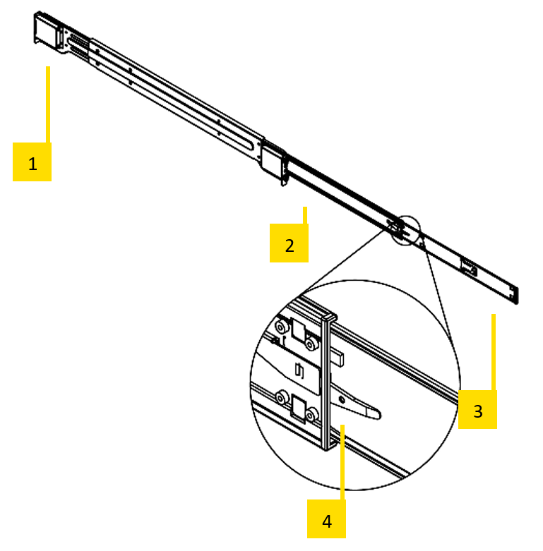
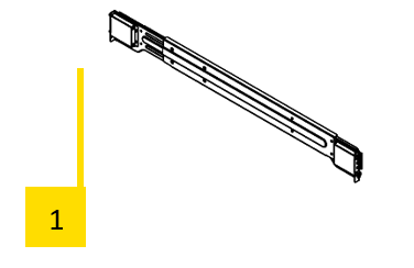
Inner Rack Rails

- Both chassis rails have a locking tab [2]. The tabs lock the server into place when installed and pushed fully into the rack. These tabs also lock the server in place when fully extended from the rack. This prevents the server from coming completely out of the rack when you pull it out for servicing.
- Replace both original inner rails [1] supplied with the server (black rails) with the inner rails from the rail kit (silver rails)
Outer Rack Rails
The outer rails are attached to the server rack and hold the server in place.

- Attach the short bracket [2] to the outside of the long bracket [1]. Align the pins of the rail with the slides. The ends of each bracket must be inclined in the same direction.
- Adjust both the short and long brackets to the correct distance so that the rail fits firmly into the rack.
- Attach the long bracket of the outer rail [3] to the front of the rack with two M5 screws and the short bracket [4] to the rear of the rack with three M5 screws.
Installing the Media Server into the Rack
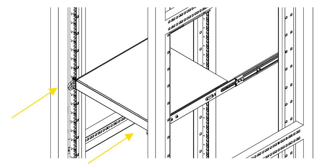
- Align the inner rails with the front of the outer rails.
- Slide the inner rails into the outer rails, keeping the pressure even on both sides (It may be necessary to depress the locking tabs when inserting). When the media server has been pushed completely into the rack, the locking tabs will "click" into the locked position.
- Insert and tighten the screws that hold the front of the server to the rack.
Mounting the Rail Kit on PX2
The package contains two rack rail assemblies in the rack mounting kit.
Each assembly consists of three sections: An inner chassis rail which secures directly to the chassis, an outer rail that secures to the rack, and a middle rail which extends from the outer rail. These assemblies are specifically designed for the left and right
Note: These rails fit into a rack with a depth between 675mm and 920mm.
- Outer rail
- Middle rail
- Inner rail
- Locking Tab:
Each inner rail has a locking tab. This tab locks the chassis into place when installed and pushed fully into the rack. These tabs also lock the chassis when it is fully pulled out of the rack. This prevents the server from fully coming out of the rack when the chassis is pulled out.
Releasing the Inner Rack Rails

- Identify the left and right outer rail assemblies as described previously.
- Pull the inner rail out of the outer rail until it is fully extended as illustrated below.
- Press the locking tab down to release the inner rail.
- Pull the inner rail all the way out.
Installing the Inner Rails on the Chassis

Confirm that the left and right inner rails have been correctly identified.
- Place the inner rail against the side of the chassis and align the hooks on the side of the chassis with the holes in the inner rail.
- Slide the inner rail forward to the front of the chassis until the rail snaps into the locked position that secures the inner rail to the chassis.
- Attach the inner rail to the chassis with the screw.
Installing the Outer Rails on the Rack

- Press the locking tab at the rear end of the middle rail upwards.
- Push the middle rail back into the outer rail.
- Hang the hooks on the front of the outer rail in the slots on the front of the rack. Additionally, fasten the outer rails to the rack with screws as shown above.
- Pull out the back of the outer rail and adjust the length to the rack.
- Hang the hooks of the rear part of the outer rail in the slots on the back of the rack. Additionally, fasten the rail to the rack with screws.
Installing the Chassis into the Rack

- Extend the outer rails as shown above.
- Align the inner rails of the chassis with the outer rails.
- Slide the inner rails into the outer rails, keeping the pressure even on both sides. When the media server has been pushed completely into the rack, the locking tabs will "click" into the locked position.
- Insert and tighten the screws that hold the front of the server to the rack.
Starting up the media server
Plug in all cables first!
Do not connect or disconnect any cables during operation. This can cause damage to the device.
Press the power switch to turn the device on and off. The power button does not disconnect the server from the mains voltage! To completely disconnect it from the mains voltage, unplug the power plug(s) from all power supply inputs.
Turn on the server when operating conditions are within its operating range (see specifications). If the unit is operated outside this operating environment, the server may be damaged.
Servicing
Removing the PX2 back panel for servicing purposes
The rear panel protects the redundant power supplies and the SSDs from damage and accidental removal.
To replace the redundant power supplies and the SSDs during service, the back panel must be removed.
IMPORTANT! Servicing activities on the server may only be carried out in consultation with AV Stumpfl GmbH. Unauthorized servicing activities will void the warranty.
IMPORTANT! Switch off the server and disconnect it from the power supply!
(Standard configuration shown, your system may be different)
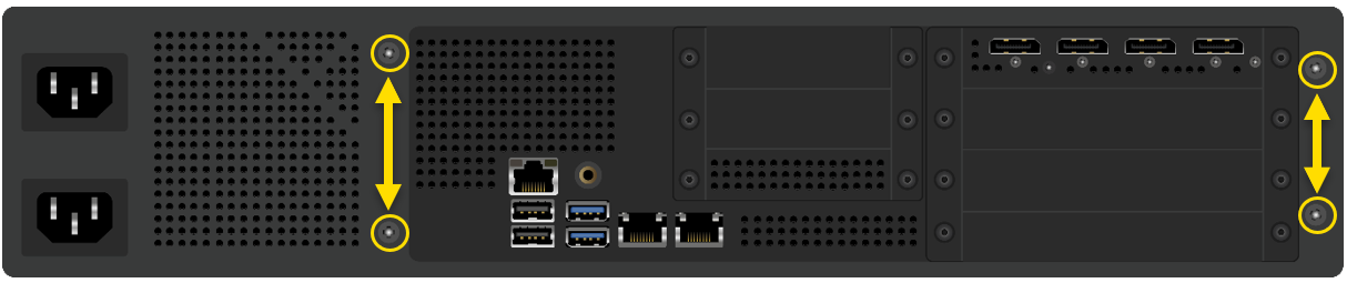
- Remove the 4 screws
- Remove the back panel
Now you have access to the power supply modules and the SSDs. Replacing the power supplies and the SSDs see the following points.
IMPORTANT! After completion of the servicing activities, the back side must be re-attached to the server! Operating the server without back panel will void the warranty.
Replacing the power supply
The PIXERA two media server has a redundant power supply. They automatically sense and operate at a 100V to 240V input voltage and are autoswiching. One power supply can be replaced without powering down the system.
A yellow lamp on the power supply unit illuminates when the unit is switched off. A green light indicates that the power is on.
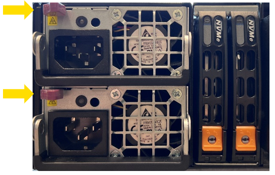
- Push the release tab on the back of the power supply.
- Pull the power supply out using the handle provided.
- Replace the failed power module with a new unit. The new power supply module must be identical with the replaced one. Power supply modules must be ordered at AV Stumpfl.
- Push the new power supply module into the power bay until you hear a click.
- Plug the AC power cord back into the module.
IMPORTANT! Please be aware that removing these parts without proper ESD protection can be dangerous and can destroy the parts and the media server!
Replacing the SSDs
IMPORTANT! The exchange of the SSDs may only be carried out in consultation with AV Stumpfl GmbH! Unauthorized replacement of the SSDs will void the warranty.
IMPORTANT! Switch off the server and disconnect it from the power supply!
After exchanging the SSDs, all data is lost. No data is stored redundantly. If you have exchanged the OS-SSDs, you must request a corresponding image of the operating system from AV Stumpfl. If you have exchanged the data SSD, you must reinstall the data.

- Take a slotted screwdriver and turn the screw to the right to unlock the SSD carrier.
- Press the orange button down to release the SSD.
- Pull out the SSD carefully.
- Replace the SSD in the carrier with exactly the same model.
- Slide the SSD back in.
- Turn the screw of the SSD carrier back to the left to lock it again.
IMPORTANT! Please be aware that removing these parts without proper ESD protection can be dangerous and can destroy the parts and the media server!
06.05.2024| R.F