 Contact Us


IMPORTANT INFORMATION
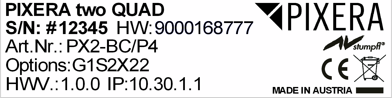
Identifying the product and other information
This instruction manual relates to media server and media player systems from AV Stumpfl GmbH.
The model designation and serial number are located on the media server’s serial number tag.
For PXm and PX1, the serial number tag is located on the bottom of the unit.
For PX2, the serial number tag is located on the sides in the recess on the back.
Abbreviations and naming used in this manual
Abbreviations:
PIXERA mini: PXm
PIXERA one: PX1
PIXERA two: PX2 (if not explicitly mentioned otherwise, this also applies to models PX2 OCTO and PX2RT)
PIXERA two RT: PX2RT
The term "media server" is used in this manual for both media servers (PX1, PX2) and media players (PXm).
General information about this instruction manual
With this instruction manual, users of AV Stumpfl GmbH media servers are provided the necessary information for the safe use of their systems.
The safety instructions resulting from the legally prescribed risk analysis and assessment are an essential part of these instructions.
- IMPORTANT! Please read these instructions carefully before using your system! Store this instruction manual in a safe place for later reference.
- IMPORTANT! Due to the high number of possible configurations, it is not possible to provide specific instructions for all the individual components in this manual.
For specific questions and further support, please contact us at:
AV Stumpfl GmbH, Tel: +43 (7249) 42811, support@avstumpfl.com
Subject to change without notice. All information is provided without guarantee and liability.
Safety information
The safety information in this instruction manual can be broken down into the following categories:
- WARNING is used for hazards that could result in death or serious injuries
- CAUTION is used for hazards that could result in minor injuries.
- IMPORTANT is used for all other cases where the potential for material damage exists or specific actions are recommended.
Target group/qualifications
The use of media server systems requires specialist AV and IT knowledge. For this reason, the use of media server systems should be limited to qualified personnel. Media server system owners and operators must ensure this via organizational measures.
The qualified personnel responsible for installation and maintenance must also be able to prevent any remaining risks in terms of health and safety with their understanding of the existing dangers.
Warning about electrical hazards
Electrical hazards can arise across a media server system’s entire life cycle. These can arise not only from the media server system, but the electrical installation on site as well.
-
WARNING! Dangerous situations can arise from the careless handling of the server system or faulty electrical installation.
These can result in severe injury or death!- Extreme care should be used when working on the media server system.
- Always consult the responsible specialists when working with dangerous voltages.
Intended use
The media server systems are meant exclusively for use in rooms with normal operating conditions (temperature, humidity, radiation) such as air-conditioned server rooms, offices and other rooms with similar conditions.
Warning about foreseeable misuse
-
WARNING! Dangerous situations can arise from using the server systems in unsuitable environments.
These can result in severe injury or death!- Only use the media server systems in professional AV and IT environments!
- The use of the media server systems in special environments, such as medical facilities, potentially explosive environments or areas with unusually high EMC requirements, is not permitted!
-
WARNING! Dangerous situations can arise from unauthorized modifications.
These can result in severe injury or death!
Do not attempt to modify the existing protections!
Installation on site
Checking for transport damages
Check the packaging and the media server system for possible damage that could have arisen during transport. If you find damage, please report it immediately to your vendor or AV Stumpfl GmbH.
-
IMPORTANT! Add-on cards can sometimes become partially detached from their slots during transport.
In this case please report it immediately to your vendor or AV Stumpfl GmbH.
Danger from condensation
-
WARNING!A difference in temperature of 15°C between the room’s temperature and the media servers can result in the formation of condensation. This can lead to short circuits and other damage. These can lead to the risk of electrocution. Electrocution can result in severe injury or death!
- Please ensure that the server system is not subject to quick changes in temperature!
- Give the system time to acclimate to its environment.
- Do not operate the server system if condensation has formed!
Danger from incorrect posture and overexertion
-
WARNING!Due to the weight and dimensions of the server system, physical danger can arise during set up and installation.
- Avoid incorrect posture and overexertion (e.g. from lifting heavy objects)!
Danger from tipping
-
WARNING! The server system can tip over from improper transport or installation. This is particularly true for rack systems that have a high center of gravity due to their construction.
This can result in severe injury or death!- Transport the system with the necessary care!
- Ensure secure installation on a flat and level surface.
- Rack systems must be anchored to a suitable firm surface!
- When installing devices into the rack, start at the lowest slot and work upwards. Install the heaviest devices at the bottom of the rack!
- Only remove one device at a time from a rack!
Installation on site
AV Stumpfl GmbH recommends installing the server in an air-conditioned server room. Select a site that is:
- Clean, dry and free of particles in the air (except for normal dust).
- Not near sources that cause vibrations or shaking.
- Protected from strong electro-magnetic fields that arise from electrical devices.
- Provides access to a properly grounded wall socket.
- Able to be equipped with surge protection, particularly in areas subject to thunderstorms.
- Provides sufficient space for access to the power cables, as these are the primary way to disconnect the server from the power supply.
- Provides sufficient space to ensure air circulation (for cooling).
Danger from noise
-
WARNING! Some server systems emit noise. Generally, this noise is produced by the system fans.
In certain situations, this can lead to hearing damage. Communication near such server systems can also be impaired.- Use care when selecting an installation site for such servers!
- There must be no permanent impairment!
Initial installation
Notes for rack system installations
Install a line disconnector for the entire rack system.
This line disconnector must be easily accessible and have a label that states that it controls the power supply to the entire unit and not just the servers.
Danger from improper voltage supply
-
WARNING! Dangerous situations can arise from improper voltages. These can lead to the risk of electrocution.
Electrocution can result in severe injury or death!- Only operate the server system using the voltage specified in this manual!
The server system can be operated in combination with an uninterruptible power supply (UPS). In this case, please follow the instruction manual for the UPS system!
Danger from improper grounding
-
WARNING! Dangerous situations can arise from improper grounding. These can lead to the risk of electrocution.
Electrocution can result in severe injury or death!- Please ensure that the server system and/or the rack itself and all incorporated devices are properly grounded!
- For such work, always consult the responsible specialists.
Proper grounding is also very important for protection against EMC interference.
Danger from fire
-
WARNING! Dangerous situations can arise from improper electrical installations. These can lead to the risk of fire.
Fires can result in severe injury or death!- Please ensure that electrical installations are properly performed!
- Always consult the responsible specialists for such work.
Operation, maintenance, modifications, cleaning and disassembly
Electrical hazards
Incidents arising from electrical hazards can occur during operation, maintenance, when making modifications, cleaning or disassembling the server.
Turn off all connected peripheral devices before opening the media server system.
NOTE: Opening the media server system will void its warranty!
-
WARNING! Dangerous situations can arise if the server system is not turned off before opening the system.
These can result in severe injury or death!- Ensure that the media server system is disconnected from the power source before opening the media server system!
- Turn off the media server system via the power switch and unplug all power cables from the outlet!
- Ensure that the media server system will not be plugged in unexpectedly by another person or that the system will unexpectedly restart after an interruption in the power supply.
Additional comments on the subject:
- The power button will NOT disconnect the system from the source of power. The server system must be completely disconnected from the source of power.
- To do this, all power cables must be removed from the electrical outlet.
- A system may be equipped with multiple power cables. In such cases, ensure that all power cables have been unplugged.
- Do not make any modifications to the power cable and do not use any cables except those with the correct specifications. Each power supply in the system must be connected to the power source via its own cable.
- Power supplies do not have any parts that can be serviced by the user.
- Never open a power supply. Power supplies contain dangerous voltages, currents and energy sources. Send the device back for any necessary maintenance work.
- The server system can unexpectedly restart after an interruption in the supply of power.
One exception is components that can explicitly be plugged in (hot-plug) or swapped (hot-swap) during operation. Please note the following safety instructions for hot-plug power supplies.
Electrical hazards related to hot-plug power supplies
Electrical accidents can occur when exchanging hot-plug power supplies.
-
WARNING! Dangerous situations can arise from the careless handling of hot-plug power supplies.
These can result in severe injury or death!- Unplug all power cables of a hot-plug power supply before swapping it out!
Avoiding data loss
-
IMPORTANT! Remember to back-up your data before performing any maintenance or any other similar work inside your media server system.
Check to ensure that your data restoration system works properly.
Disassembly and assembly of the housing
Should you need to remove the media server system’s housing for maintenance work or any similar work inside the system, make sure to store all screws and fastenings in a safe place.
NOTE: Opening the media server system will void ins warranty!
Once you have completed your work on the media server system, reassemble the housing using the original screws and fasteners.
IMPORTANT! Operating the system without its case can lead to damage for the system components. Reattach the case as follows:
- First, ensure that you have not left any tools or other parts in the system!
- Check whether all cables, add-on cards and other components are correctly configured and attached.
- Re-mount the panels onto the product’s frame!
Danger from sharp corners and edges
-
CAUTION! Despite careful selection of the components, sharp corners and edges can occur on the sheet metal housing. Plastic parts can also break during assembly or disassembly and leave sharp corners and edges.
Injuries can be the result. - Work with care and avoid sharp corners and edges.
- Wear protective gloves especially when working on the housing and when installing rack systems!
Danger of pinching
-
CAUTION! Moving parts, such as hard drive bays and caps, can pinch fingers. Injuries can result!
- Work carefully and pay attention to places where pinches can occur.
- Wear protective gloves when working on server housing!
Danger from hot components
-
WARNING!During operation, the processor and heat sink can get very hot. Burns can result.
- Do not open the system until it has cooled completely!
- Be careful when removing or installing hot-plug components to avoid contact with hot elements!
Danger from moving parts
-
WARNING! Server systems contain moving parts, such as rotating fan blades.
Contact with such components can cause injury.- Never touch rotating fan blades or other moving parts!
- Always operate the server system with the fan cover closed (if present)!
- Long hair can be caught in the fan. If necessary, use a hair net.
Danger from batteries
-
WARNING! A danger of explosion and corrosion can arise from improper battery replacements. Hazardous substances can be leaked.
Improper use can result in serious injury.- Only use the battery types recommended by the manufacturer!
- Never try to charge or open a battery!
Preventing damage caused by a lack of ESD measures
-
IMPORTANT! Electrostatic discharge can damage hard drives, circuit boards and other components.
Perform all work at an ESD workstation!
If such a work space is not available, you can achieve a degree of protection against electrostatic discharge by wearing an anti-static wristband. You can use these to keep you grounded by attaching the clip to any unpainted metal part of your computer case.
Always handle circuit boards with utmost caution. They are extremely sensitive to electrostatic discharge. Hold circuit boards by the edges.
After removing the circuit board from its protective case or the server, place it right side up on a grounded, fully-discharged surface. We recommend the use of a conductive foam pad and not the board’s protective case.
Never drag the board across a surface.
Use gloves when working with sensitive components.
Preventing damage due to improper cooling and a lack of air flow
-
IMPORTANT! Make sure that the ventilation slots are not covered.
Route all cables carefully to avoid disturbances in the air flow and avoid cooling problems.
To ensure proper cooling and air flow, only operate the system with its case fully assembled.
Preventing damage caused by unsuitable cleaning agents
-
IMPORTANT! Only use suitable cleaning agents.
A microfiber cloth is suitable for external cleaning.
Compressed air may be used to clean the inside of the server system. Please ensure that the air is applied gently and from a sufficient distance, as the components can otherwise be damaged.
Vacuum cleaners are not suitable for cleaning the inside of the media server system.
Instructions for disposal
The media server system and batteries must be properly disposed of as electrical waste at the end of their use. The disposal of electrical and electronic equipment is regulated by law. Please observe all local regulations. Disposal via household waste or ordinary industrial waste is not permitted.

Many of the materials are reusable. By following this notice, you make an important contribution to protecting the environment.
Specifications
To ensure proper operation, make sure that the following operating conditions are met for the media server.
-
IMPORTANT! When you receive your media server, place it in the environment where you will install it. Leave the server in its shipping crate at its final destination for 12 hours and do not connect it to the power supply! This resting period prevents thermal shock and condensation.
Ambient temperature
An ambient temperature range of 21°C to 23°C is optimal for server reliability. This temperature range allows the recommended relative humidity level to be maintained quite easily. The maximum admissible temperature range is between 10°C and 30°C. Please bear in mind that high temperatures have a negative effect on the components’ life cycle.
Relative humidity
Ambient relative humidity levels between 45% and 50% are the most suitable for data processing operations.
- Prevent corrosion
- Provide an operating time buffer in the event of environmental control system failure.
- Help avoid failures caused by the intermittent interference from static discharges that occur when relative humidity is too low.
The maximum admissible relative humidity range is between 20% and 80% (noncondensing).
Airflow considerations
- Ensure unobstructed airflow through the chassis.
- Ensure that air enters at the front of the server housing.
- Ensure that air exits at the openings designated for this purpose:
PXm: back and right side. PX1: back and top, PX2: back. - Ensure that ventilation openings, such as cabinet doors, for both the inlet and exhaust of the server provide a minimum open area equal to the server’s open areas.
- Take care to prevent recirculation of exhaust air within a rack or cabinet.
- Manage cables to minimize interfering with the server exhaust vent.
Scope of delivery
PXm: Power Supply Unit, Power Cable, mDP to DP Adapter, Manual
PX1: 19" Rail Kit, Power Cable, DP to HDMI Adapter, Manual
PX2: 19" Rail Kit, 2x Power Cable, DP to HDMI Adapter, Manual
PX2 OCTO: 19" Rail Kit, 2x Power Cable, 2x DP to HDMI Adapter, Manual
Warranty
We offer 2 years warranty on PIXERA media servers.
An additional warranty of total 3, 4 or 5 years is available on request.
- IMPORTANT! Please note that opening or modifying the media server voids its warranty.
Environmental specifications – operating
Temperature (altitude less than 1000m, no direct sunlight) |
10°C to 30°C |
Maximum Temperature Gradation |
10°C per hour |
Temperature De-Rating (altitude more than 1000m) |
Reduce max. temp. by 1°C per 300m |
Maximum Altitude |
3000m |
Relative Humidity (noncondensing) |
20%RH to 80%RH |
Maximum Humidity Gradation |
10%RH per hour |
Environmental specifications – storage
Temperature (no direct sunlight) |
-30°C to 55°C |
Maximum Temperature Gradation |
20°C per hour |
Relative Humidity (noncondensing) |
5%RH to 95%RH |
Maximum Humidity Gradation |
10%RH per hour |
Power supply
PXm |
PX1 |
PX2 |
PX2RT |
|
Power Supply |
100-240VAC, 50-60Hz |
|||
Power Consumption Peak |
150W |
500W |
800W |
800W |
Power Consumption Average with High Load * |
120W |
350W |
450W |
600W |
Redundant Power Supply Hot-Plug |
Not available |
Not available |
Yes |
Yes |
PXm |
PX1 |
PX2 |
PX2RT |
|
Power Consumption Average with High Load * |
Not available |
+35W |
+35W |
Not available |
Power Consumption Average with High Load * |
Not available |
+70W |
+70W |
Standard Config |
Power Consumption Average with High Load * |
Not available |
Not available |
+200W |
+130W |
Power Consumption Average with High Load * |
Not available |
Not available |
+250W |
+180W |
* Power Consumption Average with High Load = Tested with very high CPU, GPU and SSD/NVMe workload
Heat dissipation
PXm |
PX1 |
PX2 |
PX2RT |
|
Heat Dissipation Peak |
520BTU/h |
1710BTU/h |
2730BTU/h |
2730BTU/h |
Heat Dissipation Average with High Load * |
410BTU/h |
1200BTU/h |
1540BTU/h |
2050BTU/h |
PXm |
PX1 |
PX2 |
PX2RT |
|
Heat Dissipation Average with High Load * |
Not available |
+120BTU/h |
+120BTU/h |
Not available |
Heat Dissipation Average with High Load * |
Not available |
+240BTU/h |
+240BTU/h |
Standard Config |
Heat Dissipation Average with High Load * |
Not available |
Not available |
+680BTU/h |
+680BTU/h |
Heat Dissipation Average with High Load * |
Not available |
Not available |
+850BTU/h |
+850BTU/h |
* Heat Dissipation Average with High Load = Tested with very high CPU, GPU and SSD/NVMe workload
Physical
PXm |
PX1 |
PX2 |
|
Case Dimension (WxDxH) |
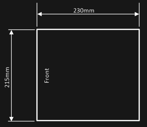
215 x 230 x 44,4mm |
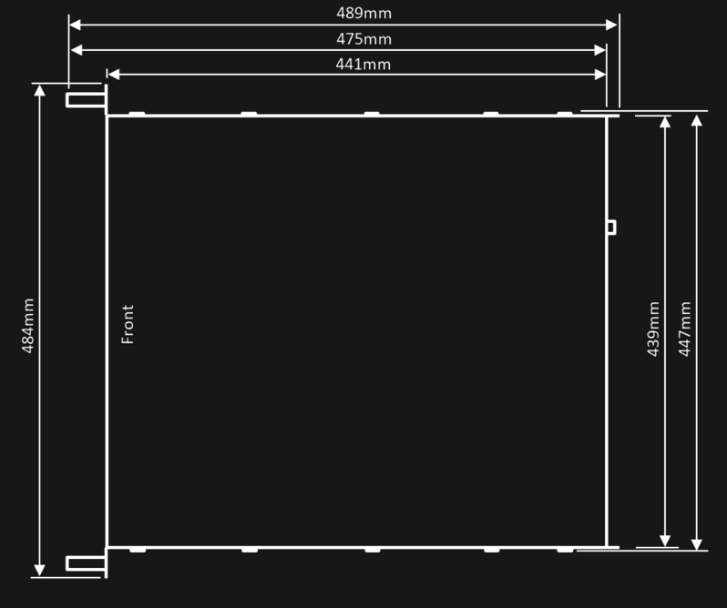
447 x 441 x 44,4mm |
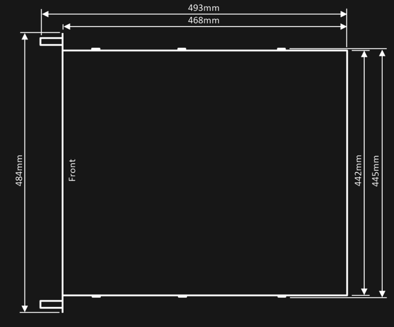
445 x 468 x 88,9mm |
Max. Product Dimension (WxDxH)* |
215 x 230 x 44,4mm |
484 x 489 x 44,4mm |
484 x 493 x 88,9mm |
Power Supply Dimension (WxDxH)* |
63 x 190 x 41mm |
- |
- |
Product Weight |
2,5kg |
8,3kg |
13,1kg |
Power Supply Weight |
0,6kg |
- |
- |
Shipping Dimension |
500 x 310 x 110mm |
660 x 580 x 160mm |
790 x 560 x 220mm |
Shipping Weight |
4,5kg |
11,75kg |
21,15kg |
PX1 with rails fit into a rack with a depth between 675mm and 850 mm.
PX2 with rails fit into a rack with a depth between 675mm and 920mm.
Dimensions
IMPORTANT! Please note that due to the production process there may be deviations in the dimensions. For exact dimensions please use the measures of the actual device.
Dimensions PXm
Dimensions PX1
Dimensions PX2
Front views
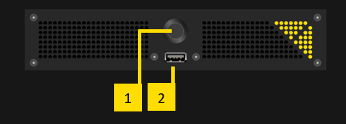
Front view PXm
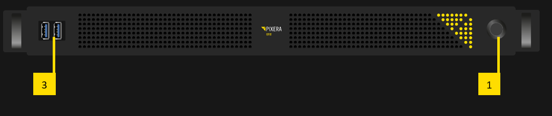
Front view PX1
Front view PX2
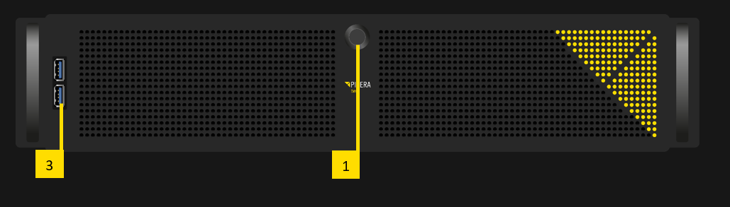
Description front views
- Power button
- USB2.0 port
- 2x USB3.0 port
Rear views
Rear view PXm
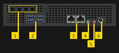
Description rear views PXm
- 4x Video Output:
- Video output standard: mDP1.4
- Video output resolution (max.): 4x 1920x1080 @60Hz or 1x 4096x2160 @60Hz
- EDID management: Yes
- Output D: left, Output A: right
- 4x USB3.0
- 2x 1Gbps LAN: 10Mbps, 100Mbps and 1Gbps speeds are supported
- Left Port = LAN1: The fixed IP address of this LAN socket can be found on the serial number label.
- Right Port = LAN2: The IP address of this socket is 1 higher than LAN1. For example, if LAN1 has the address 10.30.1.1. then LAN2 has the address
- 10.30.1.2.
- Please note that these are the IP addresses of the delivery state of the media server. All IP addresses can of course be changed individually. Please see
- the network settings of the operating system for the currently set IP address.
- Stereo Audio Output
- Mic Input
- Power Supply Input.
- Input voltage range: 19VDC/7,9A – 24VDC/6,25A
- Power: 150W
- Polarity: tip = + / shield = GND
- IMPORTANT! Using an input voltage and polarity other than that specified may damage the product!
Rear view PX1, PX2
Rear view PX1
Rear view PX2

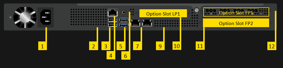
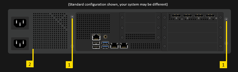
Description rear views PX1, PX2
- Socket for mains connection: In case of PX2 there are two connectors, as PX2 is equipped with redundant power supplies. Both connections must be made.
- Not used (Do not connect!)
- 2x USB2.0
- IPMI LAN:
The IP address of the IPMI LAN port is similar to the default IP address of LAN1 (see [6] below), but instead of 10.31.x.x. the address is 10.41.x.x.
For example:- LAN1 has the default address 10.31.2.3
- IPMI LAN port has the address 10.41.2.3
On newer PX Engines a password and username is required:
Username: ADMIN
Password: Px<DefaultIPaddress> (e.g. Px010031002003) (on older PX Engines the password is ADMIN)
-
- 2x USB3.0
- Stereo Audio Output
- 2x 10Gbps LAN: 1Gbps and 10Gbps speeds are supported, 10Mbps and 100Mbps speeds are not supported!
Left port = LAN1: The fixed IP address of this LAN socket can be found on the serial number label.
Right port = LAN2: This LAN port is set to DHCP. If a unique fixed IP address is required, please use 10.32.x.y, where x and y are identical with the last two digits of the IP address of LAN1. For example, if LAN1 has the IP address 10.31.2.3, the IP address 10.32.2.3 can be used for LAN2.
Please note that these are the IP addresses of the delivery state of the media server. All IP addresses can of course be changed individually. - Rear panel illumination (only available in systems shipped after Q2/2019)
- Not used (Do not connect! For servicing purposes only!)
- Option Slots LPx
- Option Slots FPx
- Always located in Option Slot FP1:
4x Video Output DP1.4. See details under "Options" – "Video Outputs".
OPTIONS PXm
NVMe option: NVMe 1TB
NVMe storage for high data rate applications.
- Option Code: M1T0
The NVME 1TB is installed internally. There are no connectors or operating controls available.
In the operating system you will see an additional drive. The drive letter can either be D:, E: or F:, depending on the configuration of the system.
The maximum constant physical read rate of this drive is 1,6GB/s. (Peak values can be higher.)
NVMe option: NVMe 2TB
NVMe storage for high data rate applications.
- Option Code: M2T0
The NVME 1TB is installed internally. There are no connectors or operating controls available.
In the operating system you will see an additional drive. The drive letter can either be D:, E: or F:, depending on the configuration of the system.
The maximum constant physical read rate of this drive is 1,6GB/s. (Peak values can be higher.)
OPTIONS PX1, PX2
Performance upgrade
The Performance Options consist of a faster CPU and more RAM. More RAM also uses more RAM channels and thus increases data throughput.
- Option Code: X27, X37, X51, X65
Option Slot PX1: no slot needed
Option Slot PX2: no slot needed
Standard Configuration:
Standard Configuration for |
PX1, PX2 |
PX2 OCTO |
PX2RT |
Option Name |
Xeon 17, 24GB RAM |
Xeon 27, 32GB RAM |
Xeon 37, 48GB RAM |
Code |
X17 |
X27 |
X37 |
Server Grade Hardware Components |
Yes |
Yes |
Yes |
CPU Type |
Intel Xeon SP Gen2 |
Intel Xeon SP Gen2 |
Intel Xeon SP Gen2 |
CPU Performance Index |
17 |
27 |
37 |
CPU # of Cores / # of Threads |
8/16 |
12/24 |
16/32 |
CPU Min/Max Frequency |
2,1/3,2GHz |
2,4/3,5GHz |
2,3/3,9GHz |
RAM |
24GB |
32GB |
48GB |
RAM Channels used (max. 6) |
3 |
4 |
6 |
ECC RAM |
Yes |
Yes |
Yes |
Performance Upgrades available:
Available for |
PX1, PX2 |
PX1, PX2 |
PX2 |
PX2 |
Option Name |
Xeon 27, 32GB RAM |
Xeon 37, 48GB RAM |
Xeon 51, 96GB RAM |
Xeon 65, 192GB RAM |
Code |
X27 |
X37 |
X54 |
X65 |
Server Grade Hardware Components |
Yes |
Yes |
Yes |
Yes |
CPU Type |
Intel Xeon SP Gen2 |
Intel Xeon SP Gen2 |
Intel Xeon W |
Intel Xeon W |
CPU Performance Index |
27 |
37 |
51 |
65 |
CPU # of Cores / # of Threads |
12/24 |
16/32 |
16/32 |
24/48 |
CPU Min/Max Frequency |
2,4/3,5GHz |
2,3/3,9GHz |
3,2/4,4GHz |
2,7/4,4GHz |
RAM |
32GB |
48GB |
96GB |
192GB |
RAM Channels used (max. 6) |
4 |
6 |
6 |
6 |
ECC RAM |
Yes |
Yes |
Yes |
Yes |
NVMe-SSD Onboard upgrade
Optional NVMe storage upgrade for data.
- Option Code: E1T0, E2T0
Option Slot PX1: no slot needed
Option Slot PX2: no slot needed
Using the onboard NVMe's, no option slot will be occupied. There are no connectors or operating controls available.
The maximum constant physical read rate of this drive is 1,6GB/s. (Peak values can be higher.)
Available for |
Standard for PX1, PX2 |
PX1, PX2 |
|
Onboard NVMe Capacity (Net) |
500GB |
1TB |
2TB |
Onboard NVMe Max. Constant Read Rate |
1,6GB/s |
1,6GB/s |
1,6GB/s |
SSD options
Please note that on PX1 and PX2 the Operating System is stored on a separate SSD (PX1: 240GB, PX2: 256GB), so the capacity of the data SSD is fully available.
Option Slot PX1: no slot needed
Option Slot PX2: no slot needed
- Single SSD:
Optional SSD for data. Installed internally in PX1 and in the primary data SSD slot in PX2.
- Code D480, D960, D1T9, D3T8, D7T8
Available for |
PX1, PX2 |
||||
SSD Capacity (Net) |
480GB |
960GB |
1,92TB |
3,84TB |
7,68TB |
SSD Max. Constant Read Rate |
500MB/s |
500MB/s |
500MB/s |
500MB/s |
500MB/s |
- Dual SSD in RAID0:
Optional 2x SSDs in RAID0 for data. Installed in primary and secondary data SSD slot.
- Code D960R0, D1T9R0, D3T8R0, D7T8R0, D15TR0
Available for |
PX2 |
||||
SSD Capacity (Net) |
960GB |
1,92TB |
3,84TB |
7,68TB |
15TB |
SSD Max. Constant Read Rate |
1GB/s |
1GB/s |
1GB/s |
1GB/s |
1GB/s |
- Dual SSD in RAID1:
Optional 2x SSDs in RAID1 for data. Installed in primary and secondary data SSD slot.
- Code D480R1, D960R1, D1T9R1, D3T8R1, D7T8R1
Available for |
PX2 |
||||
SSD Capacity (Net) |
480GB |
960GB |
1,92TB |
3,84TB |
7,68TB |
SSD Max. Constant Read Rate |
500MB/s |
500MB/s |
500MB/s |
500MB/s |
500MB/s |
Please note, that the above options cannot be combined.
Video Outputs
Video Outputs are always supplied with the Server.
In case of PX2 Option Slot FP1 is used.
- Option Code: P4
Option Slot PX1: FP1 (standard, cannot be changed)
Option Slot PX2: FP1 (standard, cannot be changed)
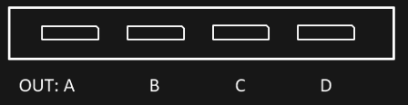
Port description
OUT A, …, OUT D: Video Output A, …, Video Output D
- Video output standard: DP1.4
- Video output resolution (max.): 4096x2160 @60Hz
- EDID management: Yes
IMPORTANT! Please note that due to space reasons DisplayPort cables need to be used where the plug does not exceed a maximum thickness of approx. 14mm!
Video Outputs for PX2 OCTO
In case of PX2 OCTO Option Slots FP1 and FP2 are used.
- Option Code: P8
Option Slot PX1: Option not available
Option Slot PX2: FP1, FP2 (standard, cannot be changed)
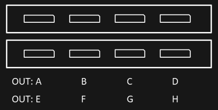
Port description
OUT A, …, OUT H: Video Output A, …, Video Output H
- Video output standard: DP1.4
- Video output resolution (max.): 4096x2160 @60Hz
- EDID management: Yes
IMPORTANT! Please note that due to space reasons DisplayPort cables need to be used where the plug does not exceed a maximum thickness of approx. 14mm!
Video Outputs PX2 RT
In case of PX2RT Option Slots FP1 and FP2 are used.
- Option Code: R6 (R8 option available)
Option Slot PX1: Option not available
Option Slot PX2: FP1, FP2 (standard, cannot be changed)
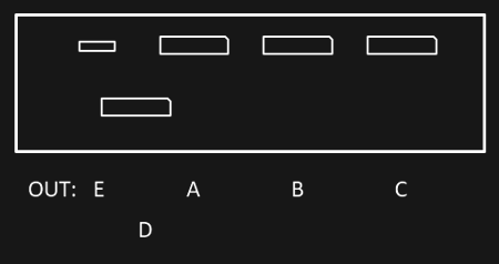
Port description
OUT A, …, OUT D: Video Output A, …, Video Output D
- Video output standard: DP1.4
- Video output resolution (max.): 4096x2160 @60Hz
- EDID management: Yes
OUT E: Video Output E
- USB-C, Adapter needed for HDMI or DP
IMPORTANT! Only four outputs can be used simultaneously.
IMPORTANT! Please note that due to space reasons DisplayPort cables need to be used where the plug does not exceed a maximum thickness of approx. 14mm!
Output option: GUI Output
Dual channel GUI output.
- Option Code: G1
Option Slot PX1: LP1
Option Slot PX2: LP1
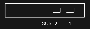
Port description
GUI 1, 2: GUI Output 1, 2
- GUI Output Standard: mDP1.4
- Max GUI Output Resolution: 4096x2160 @60Hz
- Please note that the Nvidia control panel displays four outputs. For performance reasons, only the first two of these four outputs are accessible.
Output option: Framelock and Genlock
Framelock and genlock input and outputs.
- Option Code: S2
Option Slot PX1: FP2
Option Slot PX2: FP4

Port description
FL0, FL1: Framelock 0/1 Input/Output
IMPORTANT! Do not connect to LAN! This will damage the sync card and the LAN equipment!
- LED yellow: Port is an output, but no signal is present
- LED green: Port is an input, but no signal detected
- LED yellow flashing: Port is an output and sending a signal, the frequency of the blinking is the refresh rate of the signal
- LED green flashing: Port is an input and receiving a signal, the frequency of the blinking is the refresh rate of the signal
FS: Framelock Sync Status LEDs
Shows the synchronization status of the connected video output card. The topmost LED is dedicated to video output card 1 (installed in all servers) and the second LED to video output card 2 (if installed).
- LED off: Video output card not connected. This indicates a technical problem – please contact us.
- LED yellow: Video output card not synchronized.
- LED green: Video output card synchronized.
- LED yellow flashing: Video output card synchronized, but within 5% of the threshold of losing sync.
- LED green flashing: Video output card is synchronizing.
SP: Stereo Phase Status LEDs
Shows the active stereo status of the connected video output card. The topmost LED is dedicated to video output card 1 (installed in all servers) and the second LED to video output card 2 (if installed).
- LED off: Stereo not active.
- LED green: Stereo locked.
- LED green flashing: Stereo in process of locking.
GL: Genlock Input/Output
NVMe-SSD option: 2TB
NVMe storage for high data rate applications.
- Option Code: N2T0
Option Slot PX1: LP1
Option Slot PX2: FP3
There are no connectors or operating controls available.
In the operating system you will see an additional drive. The drive letter may vary depending on the system configuration.
The maximum constant physical read rate of this drive is 4,5GB/s. (Peak values can be higher.)
NVMe-SSD option: 4TB
NVMe storage for high data rate applications.
- Option Code: N4T0R0
Option Slot PX1: not available
Option Slot PX2: FP2 + FP3
Two option slots will be occupied.
There are no connectors or operating controls available.
In the operating system you will see an additional drive. The drive letter may vary depending on the system configuration.
The maximum constant physical read rate of this drive is 7GB/s. (Peak values can be higher.)
NVMe-SSD option: 6TB
NVMe storage for high data rate applications.
- Option Code: N6T0
Option Slot PX1: not available
Option Slot PX2: not available
Option Slot PX2 RT: FP3
There are no connectors or operating controls available.
In the operating system you will see an additional drive. The drive letter may vary depending on the system configuration.
The maximum constant physical read rate of this drive is 10GB/s.
NVMe-SSD option: 4TB or 8TB
NVMe storage for high data rate applications.
- Option Code: E4T0, E8T0
Option Slot PX1: FP2, LP1
Option Slot PX2: FP2, FP3, LP1, LP2
Option Slot PX2 OCTO, PX2 RT: FP3, LP1, LP2
There are no connectors or operating controls available.
In the operating system you will see an additional drive. The drive letter may vary depending on the system configuration.
The maximum constant physical read rate of this drive is:
- In all PX1 slots 4,8GB/s. (Peak values can be higher.)
- In PX2 FP slots 4,8GB/s. (Peak values can be higher.)
- In PX2 LP slots 3,1GB/s.
NVMe-SSD option: 6TB or 12TB
NVMe storage for high data rate applications.
- Option Code: E6T0, E12T
Option Slot PX1: FP2
Option Slot PX2: FP2, FP3
Option Slot PX2 OCTO, PX2 RT: FP3
There are no connectors or operating controls available.
In the operating system you will see an additional drive. The drive letter may vary depending on the system configuration.
The maximum constant physical read rate of this drive is:
- In PX1 FP slot 6,2GB/s. (Peak values can be higher.)
- In PX2 FP slots 6,2GB/s. (Peak values can be higher.)
- In PX2 RT FP slot 7,2GB/s. (Peak values can be higher.)
NVMe-SSD RAID0 option: 8TB or 16TB
NVMe storage for high data rate applications.
- Option Code: E8T0R0, E16TR0
Option Slot PX1: FP2+LP1
Option Slot PX2: FP2+FP3, LP1+LP2
Option Slot PX2 OCTO, PX2 RT: LP1+LP2
Two option slots will be occupied.
There are no connectors or operating controls available.
In the operating system you will see an additional drive. The drive letter may vary depending on the system configuration.
The maximum constant physical read rate of this drive is:
- In PX1 slots 9,6GB/s.
- In PX2 FP slots 9,6GB/s.
- In PX2 LP slots 6,2GB/s.
NVMe-SSD RAID0 option: 12TB or 24TB
NVMe storage for high data rate applications.
- Option Code: E12TR0, E24TR0
Option Slot PX1: not available
Option Slot PX2: FP2+FP3
Option Slot PX2 OCTO, PX2 RT: not available
Two option slots will be occupied.
There are no connectors or operating controls available.
In the operating system you will see an additional drive. The drive letter may vary depending on the system configuration.
The maximum constant physical read rate of this drive is:
- In PX2 FP slots 10GB/s.
Live input option: HDMI1.4-I2
Dual channel HDMI 1.4b input (297MHz TMDS clock).
- Option Code: IH1
Option Slot PX1: LP1
Option Slot PX2: LP2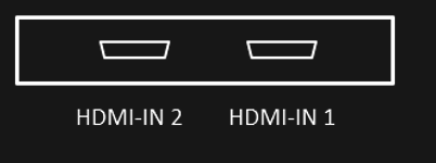
Option Slot PX2: FP2, FP3
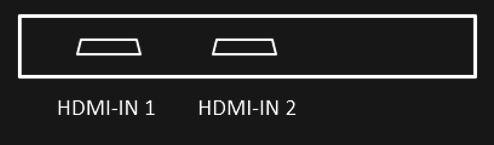
Port description
HDMI-IN 1, HDMI-IN 2: HDMI Input 1, HDMI Input 2
- Video display resolutions: up to 4096x2160@24Hz or 3840x2160@25/30Hz or 1080p@120Hz
- Support of some UHD 60Hz formats (4096x2160 or 3840x2160@60Hz in 4:2:0 8-bit) on a single port (HDMI 2.0 format)
- Graphic display resolution up to 1600x1200@60Hz
Live input option: HDMI2.0-I2
Dual channel HDMI 2.0b input.
- Option Code: IH2
Option Slot PX1: LP1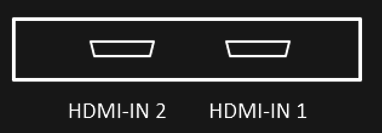
Option Slot PX2: FP2, FP3
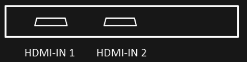
Port description
HDMI-IN 1, HDMI-IN 2: HDMI Input 1, HDMI Input 2
- Video formats: PAL, NTSC, 720p, 1080i, 1080p, 2160p (4K-DCI or UHDTV)
- Graphic formats: VGA, SVGA, XVGA, WXGA, WXGA+, UXGA, WUXGA, WSXGA
- RGB 4:4:4, YUV 4:4:4, YUV 4:2:2, YUV 4:2:0
- 8-bit, 10-bit, 12-bit, 16-bit
- Frame rates from 23.98Hz to 120Hz depending on formats
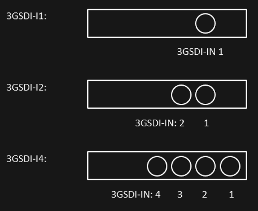
Live input option: 3GSDI-I1, 3GSDI-I2, 3GSDI-I4
Single/dual/quad channel 3G-SDI input.
- Option Code: IS1, IS2, IS4
Option Slot PX1: LP1
Option Slot PX2: LP2
Option Slot PX2: FP2, FP3
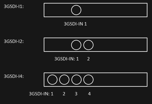
Port description
3GSDI-IN 1, …, 3GSDI-IN 4: 3G-SDI input 1, …, 3G-SDI input 4
- Video Interfaces and Formats:
- HD_292_1: S296M_720p_50Hz, S296M_720p_60Hz, S274M_1080p_24Hz, S274M_1080p_25Hz, S274M_1080i_50Hz, S274M_1080i_60Hz
- HD_DUAL_372: S274M_1080p_50Hz, S274M_1080p_60Hz
- 3G_A_425_1: S274M_1080p_50Hz, S274M_1080p_60Hz
- 4XHD_QUADRANT: 3840x2160p_24Hz, 3840x2160p_25Hz, 3840x2160p_30Hz
- 4X3G_A_QUADRANT: 3840x2160p_50Hz, 3840x2160p_60Hz
- 3G_B_DL_425_1: S274M_1080p_50Hz, S274M_1080p_60Hz
- 4X3G_B_DL_QUADRANT: 3840x2160p_50Hz, 3840x2160p_60Hz
- 2X3G_B_DS_425_3: 3840x2160p_24Hz, 3840x2160p_25Hz, 3840x2160p_30Hz
- 4X3G_A_425_5: 3840x2160p_50Hz, 3840x2160p_60Hz
- 4X3G_B_DL_425_5: 3840x2160p_50Hz, 3840x2160p_60Hz
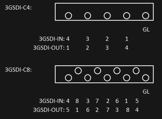
Live input option: 3GSDI-C4, 3GSDI-C8
Quad/octo channel 3G-SDI configurable input and output.
- Option Code: CS4, CS8
Option Slot PX1: LP1
Option Slot PX2: FP2, FP3
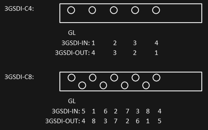
Port description
IMPORTANT! As this option does not have BNC connectors for space reasons, DIN-BNC adapters are required for operation with BNC cables.
GL: Genlock input
- Blackburst or tri-level sync reference input
3GSDI-IN 1, …, 3GSDI-IN 8: 3G-SDI input 1, …, 3G-SDI input 8
- Video Interfaces and Formats:
- HD_292_1: S296M_720p_50Hz, S296M_720p_60Hz, S274M_1080p_24Hz, S274M_1080p_25Hz, S274M_1080i_50Hz, S274M_1080i_60Hz
- HD_DUAL_372: S274M_1080p_50Hz, S274M_1080p_60Hz
- 3G_A_425_1: S274M_1080p_50Hz, S274M_1080p_60Hz
- 4XHD_QUADRANT: 3840x2160p_24Hz, 3840x2160p_25Hz, 3840x2160p_30Hz
- 4X3G_A_QUADRANT: 3840x2160p_50Hz, 3840x2160p_60Hz
- 3G_B_DL_425_1: S274M_1080p_50Hz, S274M_1080p_60Hz
- 4X3G_B_DL_QUADRANT: 3840x2160p_50Hz, 3840x2160p_60Hz
- 2X3G_B_DS_425_3: 3840x2160p_24Hz, 3840x2160p_25Hz, 3840x2160p_30Hz
- 4X3G_A_425_5: 3840x2160p_50Hz, 3840x2160p_60Hz
- 4X3G_B_DL_425_5: 3840x2160p_50Hz, 3840x2160p_60Hz
3GSDI-OUT 1, …, 3GSDI-OUT 8: 3G-SDI output 1, …, 3G-SDI output 8
- Please note that the outputs are numbered in the reverse order of the inputs.
Live input option: FLEX-C4, FLEX-C8
Quad interface for FLEX modules.
- Option Code: F4, F8
Option Slot PX1: LP1 (4 channels available simultaneously in this slot!)
Option Slot PX2: LP2 (2 channels available simultaneously in this slot!)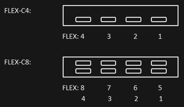
Option Slot PX2: FP2, FP3 (4 channels available simultaneously in this slot!)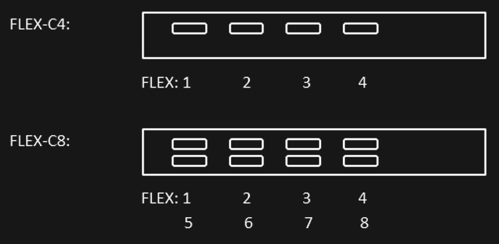
Port description
FLEX 1, …, FLEX 8: FLEX module connector 1, …, FLEX module connector 8
IMPORTANT! Do not connect to any USB-C device! This will damage the FLEX card and the USB-C device!
- Available FLEX modules (not included):
- FLEX Module DP1.2-I1: 1x DisplayPort 1.2 input (up to 4K60)
- FLEX Module HDMI2.0-I1: 1x HDMI 2.0 input (up to 4K60)
- FLEX Module 3GSDI-I4: 4x 3G-SDI inputs (up to 4x 1080p60 or 1x 4K60)
- Please use only the supplied cables.
Audio output option: HDSPe AIO
RME HDSPe AIO sound interface.
- Option Code: A1
Option Slot PX1: FP2
Option Slot PX2: FP2, FP3
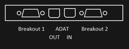
Port description
Breakout 1: Breakout cable for Analog input/output and MIDI input/output
- The 15-pin analog breakout cable has four RCA connectors (stereo analog I/O), a 1/4" TRS jack (headphones), and two 5-pin DIN connectors (MIDI I/O).
- Using the optional balanced analog XLR breakout cable, the card offers balanced Line inputs and outputs via female and male XLR connectors.
Breakout 2: Breakout cable for SPDIF input/output and AES input/output
- The 9-pin digital breakout cable has two RCA connectors as coaxial SPDIF input/output (the red phono socket is the output), and an XLR AES/EBU input and output.
ADAT IN, ADAT OUT: Optical ADAT input and output
IMPORTANT! Due to the limited space at PX1 it can be possible that special cables for some connectors have to be used!
(More details see RME manual: http://www.rme-audio.de/download/hdspeaio_e.pdf )
Audio output option: HDSPe AO4S
RME HDSPe AO4S 4 channel balanced output
- Option Code: A2
Option Slot PX1: not available
Option Slot PX2: FP3
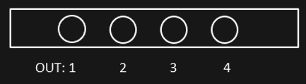
Port description
OUT 1, … OUT 4: Audio out 1, …, Audio out 4
- The short circuit protected, low impedance and balanced line outputs are accessible through stereo 6,35mm TRS jacks.
(More details see RME manual: http://www.rme-audio.de/download/ao4s192_e.pdf )
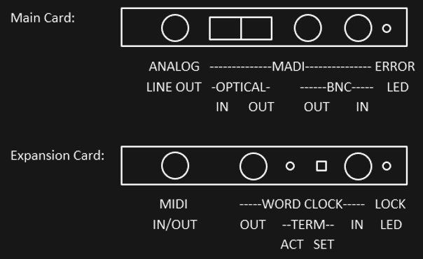
Audio output option: HDSPe MADI
RME HDSPe MADI sound interface
- Option Code: A3
Option Slot PX1: FP2 (Only main card can be installed! WORD CLOCK, MIDI are therefore not available!)
Option Slot PX2: FP2 and FP3
[!] Both slots are required for full functionality! (Note: If neither WORD CLOCK nor MIDI is required, it is not necessary to have the expansion card installed.)
Port description
ANALOG LINE OUT
- Stereo monitor output (Phones)
MADI OPTICAL/BNC IN/OUT
- Identical signals are available at both the optical and the coaxial output.
ERROR LED
- MADI error LED
MIDI IN/OUT
- The included breakout cable is connected to the 9-pin Mini-DIN connector and provides two MIDI inputs and outputs via four 5-pin DIN connectors.
WORD CLOCK IN/OUT
- Word clock input and output
WORD CLOCK TERM SET/ACT
- Between the BNC sockets, 75 Ohm word clock termination can be activated and verified by a yellow LED.
LOCK LED
- A green LED displays the word clock input's LOCK state.
(More details see RME manual: http://www.rme-audio.de/download/hdspemadi_e.pdf )
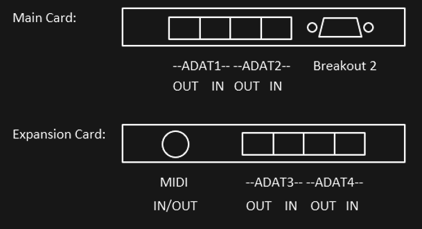
Audio output option: HDSPe RayDAT
RME HDSPe RayDAT sound interface
Option Code: A4
Option Slot PX1: FP2 (Only main card can be installed! MIDI, ADAT3, ADAT4 are therefore not available!)
Option Slot PX2: FP2 and FP3
[!] Both slots are required for full functionality! (Note: If neither MIDI nor ADAT3 and ADAT4 are required, it is not necessary to have the expansion card installed.)
Port description
ADAT1 IN/OUT, …, ADAT4 IN/OUT
- 4 channels optical ADAT input and output
Breakout 2: Breakout cable for SPDIF input/output and AES input/output
- The 9-pin digital breakout cable has two RCA connectors as coaxial SPDIF input/output (the red phono socket is the output), and an XLR AES/EBU input and output.
MIDI IN/OUT
- The included breakout cable is connected to the 9-pin Mini-DIN connector and provides two MIDI inputs and outputs via four 5-pin DIN connectors.
IMPORTANT! Due to the limited space at PX1 it can be possible that special cables for some connectors have to be used!
(More details see RME manual: http://www.rme-audio.de/download/raydat_e.pdf )
Mechanical installation
This section provides information on installing the media servers.
There are a variety of rack units on the market, which may mean that the assembly procedure will differ slightly from the instructions provided. You should also refer to the installation instructions that came with the rack unit you are using.
-
CAUTION!Never mount the media server solely on the 19" mounting bracket attached to the server. This will break the 19" mounting bracket and damage the server, the rack and may cause injury.
- Always use 19" rails (if supplied with the unit)
- Or ensure that the media server rests on an appropriate base plate.
- CAUTION! Do not pick up the server with the front handles. They are designed to pull the chassis from a rack only. This may damage the server and may cause injury.
Precautions
- Ensure that the leveling jacks on the underside of the rack are fully extended to the floor, with the entire weight of the rack resting on them.
- For single rack mounting, stabilizers must be attached to the rack.
- For multiple racking systems, the racks must be coupled together.
- Always make sure that the rack is stable before pulling a component out of the rack.
- You may only extend one component at a time - the simultaneous extension of two or more components can cause the rack to become unstable.
- The units must be installed in a rack in such a way that no dangerous condition arises due to uneven mechanical loading.
- Install the heaviest server components on the bottom of the rack first, and then work your way up.
- Use an uninterruptible power supply (UPS) to protect the server from power surges and voltage spikes and keep your system up and running in the event of a power failure.
Mounting the Vesa Mount on PXm
The VESA Mount supports 75x75mm and 100x100mm VESA.
1. Attach VESA mount to rear of screen with the tabs at the top and bottom.
2. Use M3 Screws to attach the PXm to the VESA mount, there are two holes either side for a total of four screws.
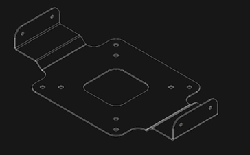
Mounting the Dual Rackadapter on PXm
The PXm Dual Rackadapter is designed to hold two PIXERA mini units as well as their external power supplies.
- Attach the male centre section to the inside face (right) of the unit to be mounted on the left-hand side (looking at the rack from the front), using four countersunk M3 screws.
- Attach the female centre section to the inside face (left) of the unit to be mounted on the right-hand side (looking at the rack from the front), using four countersunk M3 screws.
- Slide the two mating halves together and secure with two M3 screw at the rear of the centre sections to lock them together.
- Place the two joined units inside the outer rack chassis and use four M3 countersunk screws to secure each unit to the side.
- Secure the rear of the centre section to the shelf using a countersunk M3 screw.
Mounting the Rail Kit on PX1
The package contains two rack rail assemblies in the rack mounting kit.
Each assembly consists of two parts: an inner fixed chassis rail attached directly to the server chassis and an outer fixed chassis rail attached directly to the rack itself.
Note: These rails fit into a rack with a depth between 675mm and 850 mm.
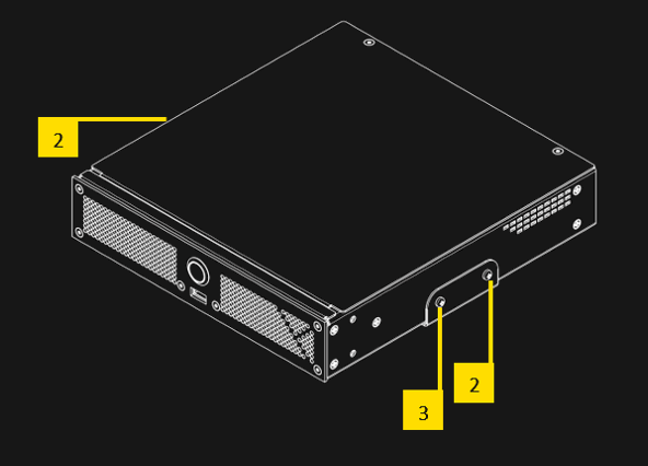
Inner Rack Rails
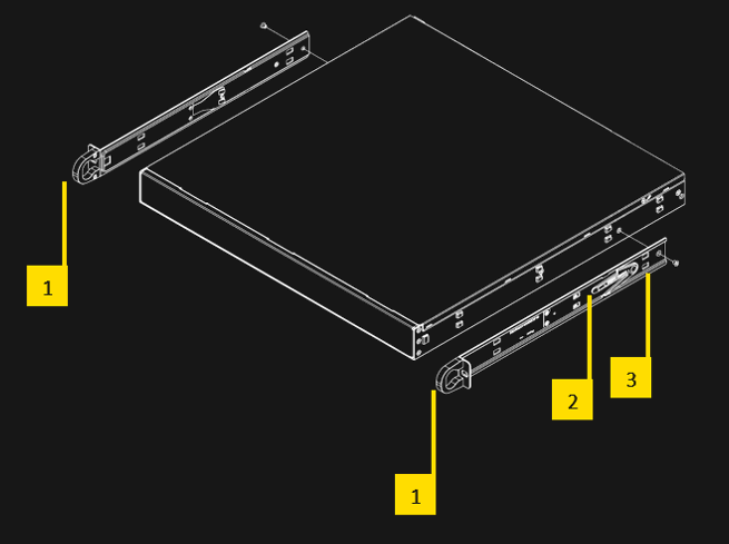
- Both chassis rails have a locking tab [2]. The tabs lock the server into place when installed and pushed fully into the rack. These tabs also lock the server in place when fully extended from the rack. This prevents the server from coming completely out of the rack when you pull it out for servicing.
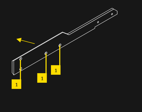
- Replace both original inner rails [1] supplied with the server (black rails) with the inner rails from the rail kit (silver rails)
- Remove the locking screw [3].
- Push the black 19" rail [1] back until the hooks of the chassis disengage from the rails.
- Place the new silver rail [1] on the side of the chassis and align the hooks of the chassis with the inner rail holes.
- Slide the rail to the front of the chassis until it clicks into place.
- Fix the rail again with the screw.
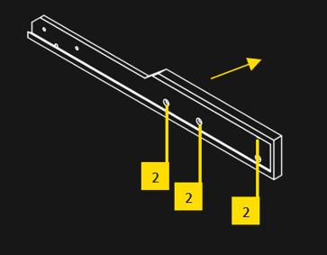
Outer Rack Rails
The outer rails are attached to the server rack and hold the server in place.
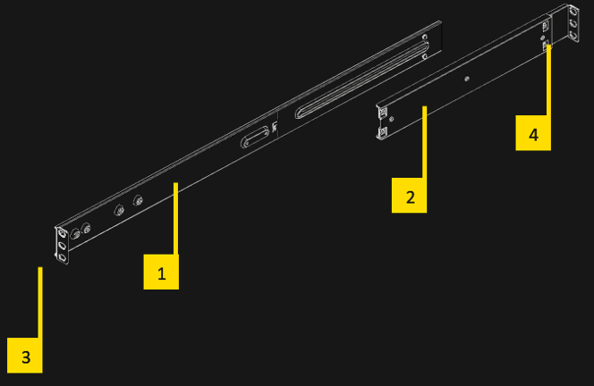
- Attach the short bracket [2] to the outside of the long bracket [1]. Align the pins of the rail with the slides. The ends of each bracket must be inclined in the same direction.
- Adjust both the short and long brackets to the correct distance so that the rail fits firmly into the rack.
- Attach the long bracket of the outer rail [3] to the front of the rack with two M5 screws and the short bracket [4] to the rear of the rack with three M5 screws.
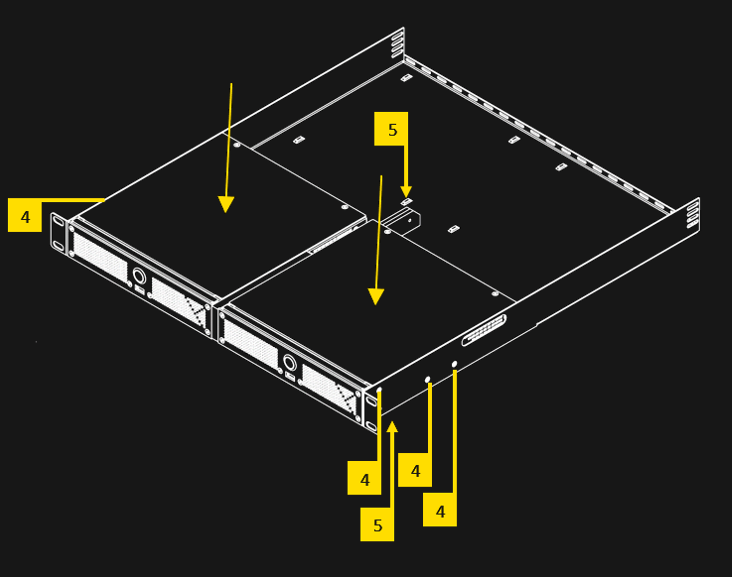
Installing the Media Server into the Rack
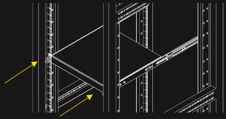
- Align the inner rails with the front of the outer rails.
- Slide the inner rails into the outer rails, keeping the pressure even on both sides (It may be necessary to depress the locking tabs when inserting). When the media server has been pushed completely into the rack, the locking tabs will "click" into the locked position.
- Insert and tighten the screws that hold the front of the server to the rack.
Mounting the Rail Kit on PX2
The package contains two rack rail assemblies in the rack mounting kit.
Each assembly consists of three sections: An inner chassis rail which secures directly to the chassis, an outer rail that secures to the rack, and a middle rail which extends from the outer rail. These assemblies are specifically designed for the left and right
Note: These rails fit into a rack with a depth between 675mm and 920mm.
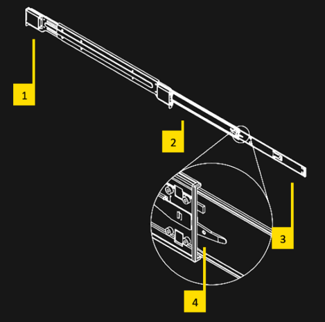
- Outer rail
- Middle rail
- Inner rail
- Locking Tab:
Each inner rail has a locking tab. This tab locks the chassis into place when installed and pushed fully into the rack. These tabs also lock the chassis when it is fully pulled out of the rack. This prevents the server from fully coming out of the rack when the chassis is pulled out.
Releasing the Inner Rack Rails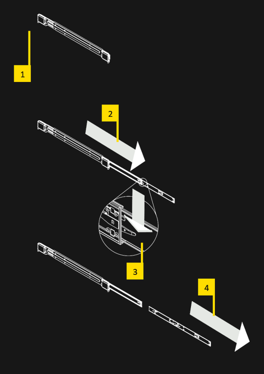
- Identify the left and right outer rail assemblies as described previously.
- Pull the inner rail out of the outer rail until it is fully extended as illustrated below.
- Press the locking tab down to release the inner rail.
- Pull the inner rail all the way out.
Installing the Inner Rails on the Chassis
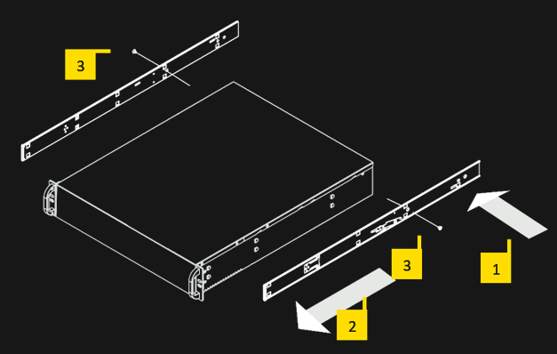
Confirm that the left and right inner rails have been correctly identified.
- Place the inner rail against the side of the chassis and align the hooks on the side of the chassis with the holes in the inner rail.
- Slide the inner rail forward to the front of the chassis until the rail snaps into the locked position that secures the inner rail to the chassis.
- Attach the inner rail to the chassis with the screw.
Installing the Outer Rails on the Rack
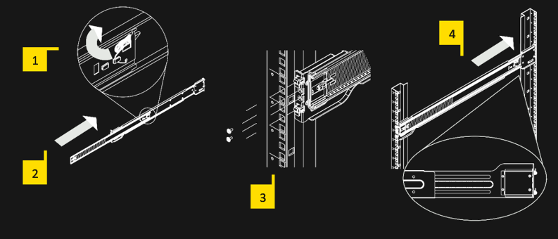
- Press the locking tab at the rear end of the middle rail upwards.
- Push the middle rail back into the outer rail.
- Hang the hooks on the front of the outer rail in the slots on the front of the rack. Additionally, fasten the outer rails to the rack with screws as shown above.
- Pull out the back of the outer rail and adjust the length to the rack.
- Hang the hooks of the rear part of the outer rail in the slots on the back of the rack. Additionally, fasten the rail to the rack with screws.
Installing the Chassis into the Rack
- Extend the outer rails as shown above.
- Align the inner rails of the chassis with the outer rails.
- Slide the inner rails into the outer rails, keeping the pressure even on both sides. When the media server has been pushed completely into the rack, the locking tabs will "click" into the locked position.
- Insert and tighten the screws that hold the front of the server to the rack.
Software
Media Server Operating System
- Systems shipped before 2020-01-01:
Windows 7 Embedded is used as the operating system.
(Please note that Windows 7 Embedded is not described in this document.) - Systems shipped after 2020-01-01:
Windows 10 IoT is used as the operating system.
The operating system has been optimized by AV Stumpfl for media server applications. To save performance and to increase stability, some components, which will be available on a standard Windows operating system, are turned off or are missing.
For the same reason the Windows Update Service is not enabled in the operating system. Bringing in Microsoft updates into the OS can cause instability and a loss in performance. The system must remain in the condition in which it was delivered!
IMPORTANT! For security reasons, the media servers must be operated in a separate network, from which you have no access to other networks (e.g. operational company networks, etc.). AV Stumpfl GmbH cannot accept any liability for damage (e.g. virus attack, loss of data, etc.) resulting from disregard of this guideline.
IMPORTANT! The media server runs on an operating system optimized for performance and stability. Any changes to the system can have a negative effect on performance and stability. It is therefore not recommended to install any kind of software on the media server. This also includes the installation of virus scanners, drivers, updates, etc. If an installation or any other manipulation is nevertheless carried out, it is no longer possible to guarantee a faultless function. Any changes to the system will also void the warranty. Exceptions are installations that have been approved by AV Stumpfl.
Standard User Names and Passwords
Windows user account
The Windows user account used by all media servers has been set as the administrator account.
The credentials are as follows:
- Username: AVStumpfl
- Password: AVStumpfl
IMPORTANT! Please do not create or use any account other than this one. Do not change the password of this user account. Changing the user account or password may cause some features, such as network shares, to stop working properly.
IPMI User and Password
- Username: ADMIN
- Password: ADMIN
Preinstalled Programs
On PIXERA servers there are important tools pre-installed. These can be found in the Windows start menu.
The following programs are pre-installed:
- PIXERA
- Wings RX
- NDI Tools
- Dante Virtual Soundcard
- Deltacast Tools
- Google Chrome (web browser)
- HWInfo (Hardware Analysis Tool)
- Notepad++ (text editor)
- ffmpeg (content trascoding)
- 7zip (archive program)
- mpv (media player)
- Filezilla (FTP Client)
- mediainfo (metadata viewer)
- audacity (Audio Editor)
- imagemagick (image conversion tool)
- graphicsmagick (image conversion tool)
- paint.net (image editing)
- vlc (media player)
- blender (3D editing tool)
- djv (media review software)
- prime95 (CPU stress test)
- furmark (GPU stress test)
- bulkrenameutility (advanced file renaming tool)
- iometer (drive benchmark tool)
- ultravnc (desktop sharing tool)
- sagethumbs (image converter)
- Mini Tool Partition Wizard (Hard Disk Partitioning Tool)
- Crystal Diskmark (Hard Disk Benchmark Tool)
- Quicktime (media player)
- Bluescreenview (Windows BSOD Analysis Tool)
- Sysinternals (Windows System Tools)
- Wireshark (Network Analysis Tool)
(NOTE! Since we always try to install the best tools on the server, the list of actually installed tools may differ.)
Resetting the Operating System
To do a factory reset just install the operating system using the provided image file. To do so just press F11 while it boots up and select your USB boot device and boot it in UEFI mode. The installation of the operating system will run completely automatically.
Please find further information about that topic in t"Pixera Server Update Guide"
IMPORTANT! All your files stored on drive C will be deleted after this step. We recommend creating a backup of all files on drive C.
IMPORTANT! In order not to lose any data, we also recommend backing up the data from all other drives.
Making Updates
Updating the Operating System
The Windows Update service is disabled to prevent an update from being performed during a show and to keep the operating system in a stable and tested state.
If you still need to install Windows Updates for security reasons, you must first enable the Windows Update service in the AV Stumpfl Settings Manager. Only then a Windows Update can be made.
IMPORTANT! The Windows Update service must be deactivated AV Stumpfl Settings Manager after the update process is complete to avoid interfering with subsequent playbacks.
IMPORTANT! Please note the above information regarding system instability and warranty loss!
Servicing
Removing the PX2 back panel for servicing purposes
The rear panel protects the redundant power supplies and the SSDs from damage and accidental removal.
To replace the redundant power supplies and the SSDs during service, the back panel must be removed.
IMPORTANT! Servicing activities on the server may only be carried out in consultation with AV Stumpfl GmbH. Unauthorized servicing activities will void the warranty.
IMPORTANT! Switch off the server and disconnect it from the power supply!
- Remove the 4 screws
- Remove the back panel
Now you have access to the power supply modules and the SSDs. Replacing the power supplies and the SSDs see the following points.
IMPORTANT! After completion of the servicing activities, the back side must be re-attached to the server! Operating the server without back panel will void the warranty.
Replacing the power supply
The PIXERA two media server has a redundant power supply. They automatically sense and operate at a 100V to 240V input voltage and are autoswiching. One power supply can be replaced without powering down the system.
A yellow lamp on the power supply unit illuminates when the unit is switched off. A green light indicates that the power is on.
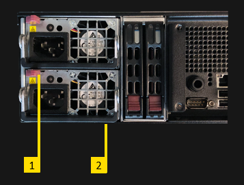
- Push the release tab on the back of the power supply.
- Pull the power supply out using the handle provided.
- Replace the failed power module with a new unit. The new power supply module must be identical with the replaced one. Power supply modules must be ordered at AV Stumpfl.
- Push the new power supply module into the power bay until you hear a click.
- Plug the AC power cord back into the module.
IMPORTANT! Please be aware that removing these parts without proper ESD protection can be dangerous and can destroy the parts and the media server!
Replacing the SSDs
- Systems shipped before Q2/2019:
The operating system is stored on the left SSD.
The right SSD is the data SSD. - Systems shipped after Q2/2019:
PX2 has an internal SSD for the operating system.
The left SSD is the primary data SSD.
The right SSD is optional and is the secondary data SSD. - Systems shipped after 2020-02:
PX2 has an internal SSD for the operating system.
The left and the right SSD are optional.
IMPORTANT! The exchange of the SSDs may only be carried out in consultation with AV Stumpfl GmbH! Unauthorized replacement of the SSDs will void the warranty.
IMPORTANT! Switch off the server and disconnect it from the power supply!
After exchanging the SSDs, all data is lost. No data is stored redundantly. If you have exchanged the OS-SSDs, you must request a corresponding image of the operating system from AV Stumpfl. If you have exchanged the data SSD, you must reinstall the data.
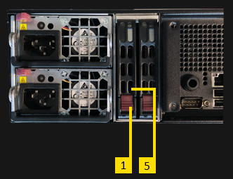
- Press the red button to release the SSD.
- Pull out the SSD carefully.
- Replace the SSD in the carrier with exactly the same model.
- Slide the SSD back in.
- Lock the SSD again.
IMPORTANT! Please be aware that removing these parts without proper ESD protection can be dangerous and can destroy the parts and the media server!
AV Stumpfl contact
If you encounter any problems using our products, please contact our Support. If you have any questions or would like to make any suggestions, you can reach us on the phone from Monday to Thursday from 8.00 to 12.00 and from 13.00 to 16.30 and on Fridays from 8.00 to 12.00 (UTC+1).
Outside these hours we can offer fee‐based emergency support:
Our emergency hotline is available every day between 8 am and 10 pm (UTC+1) at +43(7249)42811‐900. However, we would like to point out that we charge EUR 30,00 net for every 15‐minutes. Please bear in mind that we may not be able to answer your call immediately. In order to ensure that we can return your call as soon as possible and offer best‐possible support we are asking you to leave a message with your
- Company name
- Name
- Telephone number
- Dongle or customer number
on the answering machine and we will call you back.
Imprint
AV Stumpfl GmbH
Mitterweg 46
A‐4702 Wallern
Tel.: +43 7249 42811
support@AVstumpfl.com
www.AVstumpfl.com
 Declaration of Conformity

Manufacturer: AV Stumpfl GmbH
Mitterweg 46, 4702 Wallern, Austria
Tel.: +43(7249)42811-0
AVStumpfl@AVStumpfl.com
www.AVStumpfl.com
Products:
- PIXERA one
- PIXERA two
- PIXERA mini
We hereby declare that the server described above complies with all relevant regulations. It meets the requirements of the following guidelines and standards.
Applied Guidelines:
- Low Voltage Directive 2014/35/EU
- Electromagnetic Compatibility Directive 2014/30/EU
- Restriction of Hazardous Substances Directive 2011/65/EU
- Energy Related Products Directive 2009/125/EC.
Applied harmonized Standards:
Low Voltage Directive:
- EN 60950-1:2006 + A11:2009 + A1:2010 + A12:2011 + AC:2011 + A2:2013
Information technology equipment - Safety - Part 1: General requirements
Electromagnetic Compatibility Directive:
- EN 55032:2016-02
Electromagnetic compatibility of multimedia devices and equipment - Emission requirements - EN 55024:2010
Information technology equipment Immunity characteristics - Limits and methods of measurement
Restriction of Hazardous Substances Directive:
- EN 50581:2012
Technical documentation for the assessment of electrical and electronic products with respect to the restriction of hazardous substances

Wallern, 2020-03-13 Tobias Stumpfl, CEO
Version History
Date |
Document |
Hardware |
Changes |
2018-09 |
- |
V1.0.0 |
First hardware release version |
2018-09-20 |
V10 |
|
First manual release version |
2018-10-22 |
V11 |
|
Note added at port description at "Live Input Option: 3GSDI-C4, 3GSDI-C8": Rear View - #2 - changed to "Not used". |
2018-12-07 |
V12 |
|
Note added at "Rear View" – "10Gbps LAN": |
2018-12-13 |
|
V1.0.1 |
Hardware update PX1, PX2: |
2018-12-13 |
V13 |
|
Note added at "Options" – "Video Outputs": Note added at "Audio Output Option" – "HDSPe AIO", "HDSPe AES" and "HDSPe RayDAT": |
2019-01-07 |
|
V1.0.2 |
Hardware update PX2: |
2019-01-07 |
V14 |
|
Note changed at "Options" – "Video Outputs": |
2019-01-26 |
V14 |
|
"Audio Output Option - HDSPe MADI, RayDAT, AES": "Audio Output Option - HDSPe AES": Important note added at "AV Stumpfl Media Server Operating System", that any installation of software, etc. is not permitted. |
2019-02-11 |
|
V1.0.3 |
Hardware update PX2: |
2019-04-10 |
|
V1.1.0 |
Hardware update PX1, PX2: Hardware change PX2: |
2019-04-10 |
V15 |
|
NVMe Options 1TB, 2TB, 4TB added RAW-NVMe Option 4TB added PIXERA mini added (specifications, front view, rear view, options, VESA mount, rack mount) "Starting up the media server" added Note added at "Replacing the SSDs", that after Q2/2019 PX2 has an internal data SSD. UI description and Backup Manager removed (no longer available on models shipped after Q2/2019) Live input option FLEX-C8 added Rear view PX2: point "Rear panel illumination" added |
2019-05 |
|
V1.1.1 |
Hardware update PX2: |
2019-05-22 |
V16 |
|
- DVI live input options removed (EOL) - HDMI1.4 live input option added - Position of the serial number tags added under "Identifying the product and other information" - Document renamed |
2020-01-23 |
V17 |
|
- Default IP address range and default DHCP settings changed to new default values. - Manual updated to Windows 10. - Sections added: Windows User Account, Preinstalled Programs, Startmenu, PIXERA Hub, EDID Management, Genlock and Framelock Setup, Mosaic Setup, CLI programs to change screen resolution, setup mosaic and set sync, Resetting the Operating System, Making updates. - Login for IMPI added under "Standard User Names and Passwords" - Dimensions of 19" racks added under Specification – Physical. - Scope of delivery changed |
2020-01-23 |
|
V1.2 |
- New hardware config upgrades and options 2020 added (CPU standard values, performance upgrades, onboard NVMe, NVMe options, RAW removed, SSD options) |
2020-03-11 |
V18 |
|
PXM added to CE cert. |
2020-09-25 |
V19 |
|
CPU X27 updated by Intel: CPU frequency, power consumption, heat dissipation changed Option Code N4T0 changed to N4T0R0 Hint for uncompressed playback license removed at N2T0 and N4T0R0 New NVMe-SSD options added: N6T0, E4T0, E6T0, E8T0, E12T, E8T0R0, E12TR0, E16TR0, E24TR0
|